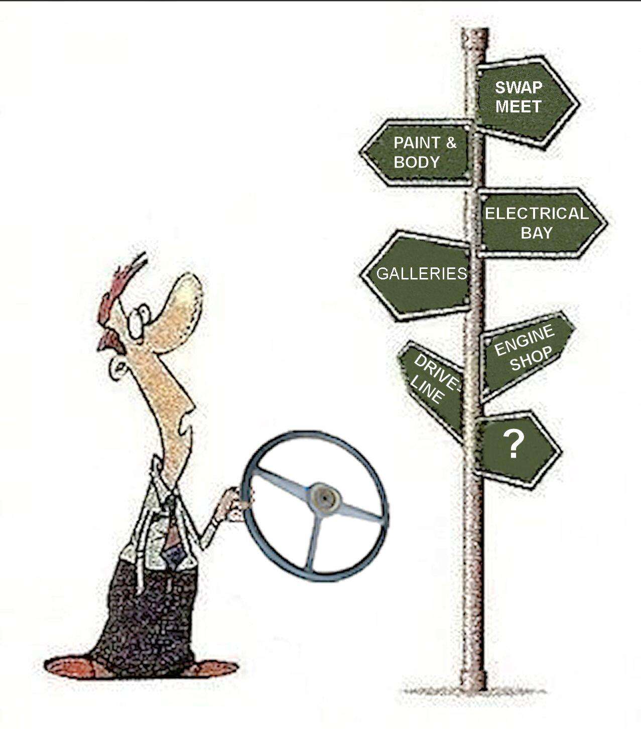
BUSY BOLTERS Are you one?  The Shop Area The Shop Area
continues to pull in the most views on the Stovebolt. In August alone there were over 22,000 views in those 13 forums.
| | Click on image for the lowdown. 
====
| | |
8 members (booger, Mike Roache, 32vsnake, COCOE, cmayna, 1955 1 Series, festerhairball, Jon G),
454
guests, and
1
robot. | | Key: Admin,
Global Mod,
Mod | | | Forums66 Topics126,777 Posts1,039,265 Members48,100 | | Most Online2,175
Jul 21st, 2025 | | | | Joined: Dec 2011 Posts: 402 Shop Shark | | Shop Shark Joined: Dec 2011 Posts: 402 | I replaced my wiring harness (Classic Parts 'original' type loom) two weeks ago. All seemed well, but I added an inline fuse or two because it just feels wrong not to have something protecting the wiring. Probably should have gone with Painless, but I was literally looking for 'plug-and-play.' The harness itself was good, but I really disliked the plastic instrument panel lite sockets. They were hard to snap in and the one for the left turn indicator broke two of the flimsy tabs that hold it in place with "spring" pressure. I replaced it with one of my old metal ones from the old harness.
But that's not what I wanted to ask about...
Since replacing the harness, my fuel gauge has started acting up. It now only displays a reading when the truck is started and running. Not when the key is turned to the 'on' position, as it used to before. Funny thing is, I would have sworn it worked as before for a day or two after I changed the harness.
At any rate, does someone have a test procedure I can run on the wires to determine if something is wrong, or have I somehow connected it wrong? I followed the numbered wiring connections exactly.
While we're at it, just before I changed out the loom, the temp gauge stopped working. Abruptly. I have tried grounding the sending unit wire with the key on and it does not move. Wires are connected correctly.
Anyone have a test procedure for these two gauges?
Thanks in advance,
Jim
| | | | | Joined: Dec 2011 Posts: 402 Shop Shark | | Shop Shark Joined: Dec 2011 Posts: 402 | I checked and have variable resistance at the sending unit when hot and cold (.45 when cold, .12 when hot). I am sure that translates to a set number of ohms but I haven't taken the time to figure out what it is I am reading. It's on the 20 ohm scale, if that helps.
At any rate, with the sender okay, guess that means it's my gauge.
I have an old temp gauge that I suspect is just as bad. Can anyone help with a test procedure for the temp gauge? | | | | | Joined: May 2005 Posts: 1,624 Shop Shark | | Shop Shark Joined: May 2005 Posts: 1,624 |
If you do a search of the forums, you will find this discussed several times. That said...
A varible resistor (0-200 ohms) is a very good 'tool' for testing both gas and electric temp gauges. Temp. gauge test...remove wire from sensor. Hook test clips from varible res. to good ground and sensor wire, Turn key on and move res. shaft (make sure you have one clip to the resistor post that varies the resistance). Watch gauge, it should move between cold to hot. BTW, as I see it, your resistance readings don't look correct.
Gas gauge test. With VOM set to DC volt, 0-25 volts or so, put one lead on the gauge +12 volt post. The other lead to ground. Switch key to run or accessory position. You should read 12 volts. If you don't, your wiring is incorrect. Good luck
Six volt guy living in a twelve volt world
| | | | | Joined: Dec 2011 Posts: 402 Shop Shark | | Shop Shark Joined: Dec 2011 Posts: 402 | Thanks Beltfed,
Guess I will need to look for a variable resistor...thingy...They have these at FLAPS or Radio Shack?
Will go through the test processes as described. You mentioned my readings don't look correct. If I am using the ohm meter, with one lead to the "nail head" on the sender and the other to ground, what should my readings look like? I was just content that there was a difference and that it appeared the resistance was lower in the hot condition. What am I missing?
Incidentally, I always search the forums carefully before posting. I use the google search on the site and straight from google as well (just in case) using the "site:" keyword. Came close with the results, but nothing that directly answered the test procedure question for TF series, in my opinion. But...point taken.
Best,
Jim
| | | | | Joined: May 2005 Posts: 1,624 Shop Shark | | Shop Shark Joined: May 2005 Posts: 1,624 | The ohm difference between cold and hot vary depending upon the type used, about 100 ohms between the two seems about right, it might be more or less. They are a matched set like the gas gauge. Some gas gauges senders are 0-90 ohms, some are 78-10 ohms, you gotta know what you have or need.
You can calibrate both your temp gauge and gas gauge with the variable resistor. I hold my gauges to + or - 2 percent.
Six volt guy living in a twelve volt world
| | |
|
|