| |
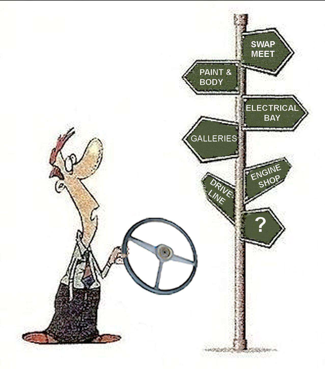
BUSY BOLTERS Are you one?  The Shop Area The Shop Area
continues to pull in the most views on the Stovebolt. In August alone there were over 22,000 views in those 13 forums.
| | Click on image for the lowdown. 
====
| | |
7 members (JasonP, Peggy M, JW51, TooMany2count, Ponchogl, 32vsnake, Gib70),
565
guests, and
1
robot. | | Key: Admin,
Global Mod,
Mod | | | Forums66 Topics126,778 Posts1,039,291 Members48,100 | | Most Online2,175
Jul 21st, 2025 | | | | Joined: Mar 2014 Posts: 11 New Guy | | New Guy Joined: Mar 2014 Posts: 11 | Looking for some electrical Help. I am trying to install Autoloc Momentary Switches to power my windows. The Switches are Keep It Clean 19MM Momentary Billet Buttons with LED Rings and using the associated Plug and Play Harness. The Relays are The Speedway Engineering Relays and Harnesses. Bosch type Relay. 30/40 amp.
The Power Windows work when wired, without relays, using a standard power window switch. No issues.
When I wire the Windows with the momentary switches, as defined by Keep it Clean / Autoloc, the LED activates and I hear the relay click, and I get 12V to one of the circuits to the power window motor - but I appear to have a problem with the return ground - and I have no idea how to overcome this problem. I know it’s the ground - because I can get a button to work if I jury-rig it with the old power window 5 lead switches on the “return leg” as this provides me the ground I appear to be missing.
I have follow and retraced stepsIn the Autoloc diagram - I have the same behavior with all 4 switches.
The only thing I am doing different than the Autoloc Diagram is the 87a ground. I can’t ground 87a, as it gets power when I activate the switch (as it should, I believe) and causes a short that fries the fuse.
I put a meter on the relay and here is what I found - without activating the switches. 85, 86 and 87 are all hot. 30 and 87a are not. When I activate the switches, 30 and 87a then are hot.
Thoughts and ideas where to go would be great | | | | | Joined: Jun 2012 Posts: 1,747 'Bolter | | 'Bolter Joined: Jun 2012 Posts: 1,747 | Look at this site. Scroll past the pictures of what is inside, and you will find a Hook up diagram. According to the diagram, 86 is ground. 85 is from the switch. 87a is normal closed. And 87 is normal open. 30 is power to the relay. I hope this helps. It would appear that the issue is 86 not to be power, it is the ground. Could just be a misprint in the instruction sheet. Let us know how it goes.
Steve H
| | | | | Joined: Jun 2012 Posts: 1,747 'Bolter | | 'Bolter Joined: Jun 2012 Posts: 1,747 | Missing link: http://www.bcae1.com/relays.htmOriginal has left the building
Steve H
| | |
|
|
| |