I've had the panel truck for almost 30 years and daily driver for 10. I started this build Two years ago, so I'll post a little build history each week until I'm caught up to real time progress.
I farmed out the heavy lifting and now work on what I can. Before I get too far will it work? Here is what I mocked up.
The wheelbase is the first thing I considered when determining a donor frame. The 1947.2 wheelbase is 137". The 1988 K2500 single cab long bed wheelbase is 131.5".
The frame width is going to have to work. 1947 1 ton is about 35", the 1988 K2500 is 45". There needs to be 5" of clearance outside of the '47 frame for this to work.
There is about 10" between the frame and running board.
The '88 frame drops 8" under the cab. The '47 battery tray will need to be trimmed. I'll replace the battery tray with a box for storage or electronics.
Last edited by Phak1; 04/15/202510:56 AM. Reason: Added as found photo
I was concerned with ride height, so I measured from the top of the frame to the bottom of the springs. The ’47 is 10", the ’88 is 13". If I place the ’47 body on the ’88 frame, the relative position of the wheel to the wheel well will be 3" greater than the stock ’47.
The ’47 has 2" wood mounting blocks. There are rails across the bed underside. The bed can be mounted closer to the frame by removing the wood blocks and modifying the rails. It looks like I can set the ’47 body on the ’88 frame and maintain the stock ’47 stance.
I have LT245/75R16 tires on the rear currently. Those are about 30" tall. If I maintain this stance, the space between the top of the rear tire and the fender will be 4". The fender opening is 31" so I won’t run a taller tire without modification.
This rear end is from an ’86 suburban. I chose rims for clearance of the tie rod ends, so ~4" back spacing. There is some room to move the wheels in with greater back spacing. I’ll get exact measurements for that. I planned on keeping the 8 lug rear axle, and modifying the front of the donor rig to 8 lug.
The rear tires are 74" wide and the front tires are 63" wide on the ’47.
The ’88 tires are 71". This will move the tires out 3.5" on the ’47. With an adjustment to the wheel back spacing, the tires should fit inside the fender.
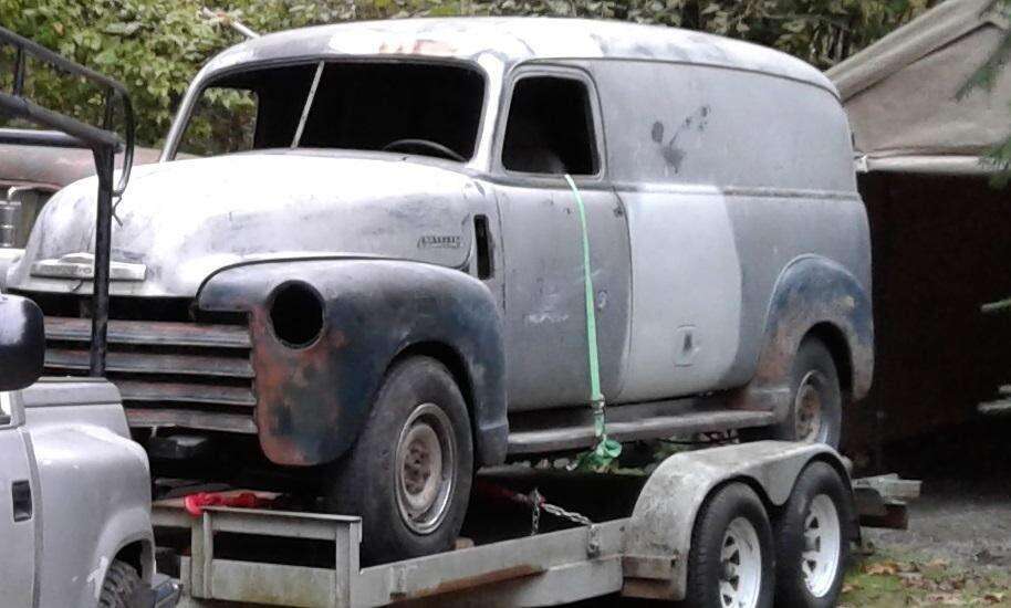
Two years ago (9/2019) I drove my panel truck for the last time, as it was, to the resto shop. A week later I drove the ’88 GMC there, the panel truck was being dismantled and they hit me with a healthy bill. One of the stipulations of the contract is that we meet once a week to go over progress, keep motivated, and settle up the bill. Each week I visited the shop, a little progress being made. They stripped both trucks down faster than I could have. The body was on a cart, and the two frames were side by side. Comparing body mounting points and deciding how to modify the donor frame. The ’47 gas filler is on the passenger side. 1988 the filler is on the driver side, tank is inside the frame rail. Pre ’88 the tanks were outside the frame and an auxilliary tank could be added to the passenger side. That doesn’t appear to be an option here, the ’88 auxiliary tank was behind the axle and I want the spare tire there. It could be done, re-route the exhaust to the driver side and find a tank with the passenger side filler. There is the driver side transfer case, so exhaust would go below that. I decided to go with moving the filler to the driver side on the panel. We used the brackets and frame ends from the ’47 frame. The original frame had extensions on the rear. We decided a frame bracket template would be a good way to locate the body mount brackets. With the Z-axis points determined, I want the body to ride at or near stock height, so the 2” wood blocks won’t be used. The 2” hat channel cross sills will be replaced with 1x2 tubing layed flat. This will put the bed as close as possible to the frame. All other mounting points are lowered about 3” relative to the bed mounts. Now all the brackets can be tacked in place, and the body will be test fit.
12/2019 The ends of the ’47 frame were cut and grafted to the donor frame. The rear frame extension is offset lower for two reasons. The body will be closer to the frame so the rear bumper will be lower relative to the frame, and there is a rear cross sill attached to the body that mounts on top of the frame. The rear end was moved back. The front frame ends are narrower on the ‘47, They tried to use them, but decided to just fabricate something. The plan was to measure everything again and bolt the rear in place. With the rear bolted in, roll it over to the alignment shop. After it’s dialed in, the rear hangers can be welded. I decided to leave the six bolt lugs for now. The 8 lug rear from the ’86 suburban is narrower between backing plates. I don’t know how the wheel mounting surface to wms compares to the ’88 6 lug. The 8 lug rear could fit with some modification. This can be done later, as the focus has shifted to the best use of funds to keep the project moving. The body mounts are tacked in place and the engine is back on the frame.. A few bed boards are being used to locate the new 1” cross sills(1x2 tube). Next step is to mock up the body on the frame.
The body is on the donor frame, (it has a 2x4 under the front in the picture), still needs some adjustments. The bottom of the firewall above the transmission will be modified. The rear of the rear inner wheel well will be trimmed to accommodate the leaf spring. The 1x2 cross sills have the bed as low as it can go without major mods. The next step is to hang the fenders, start carving the front inner fenders, and locate the running board brackets. The front and rear running board brackets have conflicts, so will need to be moved. The radiator will need to negotiate it’s placement based on the location of the steering gear. It was a good feeling to see the body on the frame, this is a good milestone in the build. There is still a long way to go, but this is a positive turn.
The rear fenders are set in place, and the runningboard brackets placement are being located. You can see where the Mr. Peanut was removed from the side, and the 5¢ on the door. The rear tire is inside the fender, I’m curious how the front tire will be. The rear wheel might could be moved ½” forward to center in the wheelwell. I didn’t measure, but it looks like the distance from the top of the tire to the wheelwell is close to the 4” = stock height. In my preliminary plans I figured the stock height could be preserved if we removed the 2” wood blocks, and replaced the 2+” hat channel cross sills with 1x2 tube. After teardown and using the body/frame template, we thought it would have a 2” lift. Now that it’s coming together, things are lining up well. There is plenty of clearance between firewall and engine. The firewall had to be modified just above the transmission, but not much. Next steps are to attach the runningboard brackets, modify the front inner fenders. Once the front fenders are in place, the core support will be addressed.
I like how the front tires don’t stick out of the fenders, they are just inside. I may be able to run wheels with a greater positive offset to suck the tires in. The fan and fan clutch are being greedy in the core support area. The plan was to get the grill and support panel mocked up and see how a radiator will fit.
Things continued moving along. The front sheet metal is being fitted. Time to get everything mocked up, so I delivered some parts last week. Awhile ago I picked up a new GM steering column from someone who gave up on a jeep project.
While I was looking for similar builds, I saw on a build that used a Kugel Komponents Brake bracket. I called them and ordered separate Brake and Clutch brackets since they didn’t offer a separate clutch bracket. I need the clearance for the stock brake booster. Ordered on Tuesday, arrived on Thursday, Wow! I also went to the parts yard and cut a fuel filler door panel out of a Nissan, that was fun᠁
While all the heavy lifting was being done at the shop, I was busy back at the bench figuring how to run the original speedometer from the electronic signal of the newer transmission.
The grill being fitted. I got some seats from a Chevy Caravan. Mocking up the steering column, pedals, and seat. The steering column is in as well as the Brake and Clutch assemblies. They used a section from the donor steering column to join the GM column to the donor shaft, needed about 7”. We also took the hole from the donor firewall. The pedal assemblies are in place. Still need to put in the donor gas pedal, and the foot starter bracket. The gas tank has been repositioned a little forward and a little down for clearance issues. The fuel filler door is in place. It looks like the battery will sit under the passenger seat. The original location was under the passenger floor, but with the wider frame that won’t work. There is an access cover under the seat, the battery can be lowered in and rotated to sit towards the outside. The exhaust runs through that area, but there’s enough room for a battery. The other option is to have the battery high on the inner fender, under the seat is a cleaner option.
6/2020 The fuel filler door, looks like they had a hell of a time with that. It is what it is. We now have a bracket for the parking brake lever. Still working on the bracket for the foot starter linkage. The foot starter linkage will not include the arm that attached to the starter. It will just be the foot pedal and the curved bracket that it is attached to, and will mount on the body to actuate a momentary button. The plan is to have that done by next week and remove the body from the chassis to finish the welds on the body mount brackets.
I have been working on the radiator issue. The steering gear interferes now, and I am running the stock ’88 fan and fan clutch. I looked at using the original radiator shifted up or out at the bottom, there just isn’t room to go up much. I looked at using the ’88 radiator, I even tried a ’70 camaro radiator for fit as I read that might work. There are brackets behind the front grill that restrict that area. I drew up some plans and went to the radiator shop for feedback. They suggested I go with a modified downflow, mock it up in cardboard for fit. So that is what I did. My builder changed the core support bracket to accommodate a radiator. I drew up some final plans and am ready to go back to the radiator shop to have a custom radiator made. I will use the stock ‘50’s top tank (20”) and have the bottom tank cut down to just under 18”. There is a band on each side of the core, so the max width will be 18” with the core just under that. 25” tall with the frame and core support being different from stock there is room to go lower. We’ll use 2-row dimpled core, so I’m hoping it will be thin enough to not have to cut into the latch panel much. The top tank will be offset to the rear. I had been running a 235 inline six with the stock radiator mounted to the front of the core support, so there is about a 1 ½” cut out in the latch panel. The radiator should look right when in place. I’ll ask if we can fit in an oil cooler in the 2”x 18” gap.
The body is back off the frame, Body mounts are being welded on. The rear runningboard bracket conflicts with the spring perch. I collected the bed wood. I’ll glue up the cracks, clean it up, and finish. The wood is in pretty good condition considering the age. I had created a spreadsheet of parts early on for the build. I started with a Jim Carter catalog. Went page by page, adding to my spreadsheet whatever I thought was needed. The list is in no particular order, so it’s kind of jumbled, but it works. I then went through an LMC catalog since I had one in hand. Classic parts website next. I have a list of each part with the price difference. I found most of the parts from these three suppliers, but there are some things that I had to search for. LMC has some good generic options that I couldn’t find at JC, or CP, like aftermarket seatbelts. I added Ecklers, they have specific parts I couldn’t find elsewhere, such as hood hinge bolts. I’m adding a door lock to the drivers side and since I already have a left hand housing, I just needed the key cylinder. Chevs of the 40s has the left door lock assembly for 1941-1948 cars. I found just the cylinder at autopartsobsolete for $20 less than the whole assembly. I’m adding rear lights from a ’39 sedan. I found about 3 different makes from several vendors. Olddogstreetrods had the ones for me, but they did not include the gasket. I found the gasket at the Filling Station, they had some other interesting parts. I got a hood side emblem from them. At this point I wasn’t going through my entire spreadsheet to compare all the prices, just select pieces. ClassicPartusa has the doorlock gasket, and spring for the rear door lock rod. Simple little things, maybe I’m not looking in the right place, but I couldn’t find those parts elsewhere. I also read about an alternative part for the rear door bumper from 80/20 Inc. I had read about Steele Rubber, so they are on the list. I’m going to really have to want their product since the prices a quite a bit higher. I placed an order from Jim Carter, and Classic Parts awhile ago. Last week I decided to get more stuff, so I placed orders with Ecklers, Chevsofthe40s, and Filling Station. Now that the frame has been worked out it’s on to the bodywork, prep for paint. I may be getting ahead of myself, but I don’t want to wait for some parts that I could have ready to go.
The frame is painted, next step is put the engine back on and reconnect the exhaust, and set up the parking brake cable. We’ll swap the left and right rear brake cables and locate the ends near the middle on a bracket. They will connect to the lever mounted to the right of the transmission. Painting the firewall and under body so the body can go back for the last time. Meanwhile I have been working on the speedometer drive, and refurbishing the speedometer. The bedwood is in pretty good condition, so I’m reworking that.
The engine is back on the frame. Firewall is painted. I’ve told the builder to wrap it up. I’ll be hauling this home soon to take on the wiring etc. Once I get it home, progress will take a slower pace as will the outpouring of funds(my primary objection). I have decided to tackle the exhaust myself. It looks like the original hanger can be used and the pipe will be extended behind the muffler. As you may be able to see in the picture it only took cutting it up to figure this out. Actually looks like it originally dumps in front of the rear tire, so may not need to be extended at all. These little side track issues add up when it’s all billable time, just the nature of the beast. I’m not saying I could do it better myself, but I don’t know if I could do worse᠁ I checked in yesterday and the body is on the frame. The lower rear corners are being repaired where the only rust through on this truck is. There is a significant dent above the drivers door, and a dent in the hood. There is also a crack in one of the rear doors. Once this body work is done, I’ll take it home. The bed wood is in good condition, so I reworked it. There were a few cracks on some boards. Here is a link to a post about the bed wood: https://www.stovebolt.com/ubbthread...store-original-bed-wood.html#Post1381523
After a year at the shop, I brought the Beast home, placed in a tent and began checking things out. I moved the boxes of old parts out and started surveying things. I made a list of what and when to do. I finally heard back from the Radiator shop with an estimate so I’d be getting the radiator soon. I’ll be able to test fit it myself. They will tack the brackets on, if it fits well, I’ll have them finish it. I took the driveshaft to get it extended 4 ½ inches. (oops! Should have been 5 ½”, I’ve had 3 driveshafts custom cut on various vehicles and always get it wrong. Measure once and cut twice or something like that.) I had refaced my speedometer, but discovered the high beam indicator lens was deteriorated. I found a refresh kit, so had to wait a week for that. After reassembly, the display would not read above 20MPH. I tore it apart again and discovered the spindle was independent of the speedcup. I glued the spindle and tried again. It took forever to get to top speed, and seemed to hang high before dropping. I tore into it again and found the speedcup binding. I removed the superglue, shimmed the speedcup and glued the spindle again, and again I didn’t get the orientation of the speedcup-to-stop correct. It didn’t rest firmly at 0. It was also binding again. I found that I could get just enough wiggle room to get clearance. I was able to loosen the screws of the speedcup assembly and spindle bracket and shift it enough to work. Once there was free movement, I looked at the stop tab. The speedcup tab was just past the stop tab, so I rotated it around and past the stop tab. I had to bend the stop tab up and then back to get the tab on the speedcup past. This put one revolution of tension on the spring. Now it didn’t read full scale, couldn’t overcome the spring tension. I tried to put it back and in the process of bending the stop tab, the tab broke off. I let the speedcup in it’s relaxed state, preset the spring by about 20 degrees, and glued a piece of wire as a stop. Upon reassembly, the old needle had a visible fracture, it broke. $8 and a week to wait, I glued the needle, and reassmebled. Now this old speedometer is working smooth and quiet.
I got a call from the radiator shop. I went to get my custom radiator for a test fit, they helped me load it into my pickup, and I asked if they wanted some money. He said I’d be back to have them attach the brackets and paint it. It is a pleasure doing business with someone who believes in the honor system. Although he was surprised when I returned later that same day with the position of the brackets already figured out. The fab shop left a brace tacked to the front of the core support that needed to go, so I needed to come up with an upper core support. I cut a length of hat channel from a bed cross sill that was removed. Fired up the ol’ Oxy Acetylene rig and had at it. I don’t have much time welding, but it came out o.k. except for one blow through. I’ll finish those welds later, probably remove the core support for that. I did weld the lumber rack that is on my pickup with Oxy Acetylene and it’s holding up so far. The custom radiator fits well, the sheet metal won’t need to be altered. The latch panel had been previously cut to accommodate the old radiator mounted to the forward of the core support. This new radiator does stick up a bit, I may be able to lower it a little, but I’m happy as it is.
1/2021 Progress is slow, but steady. I’m lucky to get 2 hours a week in on this. In the last year I have chipped away at various tasks. I moved the rear shock brackets, axle bumps, and spare tire hanger back. I modified one shock bracket to fit where the frame narrows. I don’t have much experience welding, but I did watch a video where someone welded a patch panel without using any welding rod. I tried something like that here where I heated up the metal until it melted together, it seems to work.
I have also been working on the speedometer drive. I will be using the original speedometer with this modern drivetrain, so I have connected a motor to the speedometer. I finally hooked it up to a 90 chevy truck and tested it out, here is a video I made of the 47 speedometer running next to the 90 speedometer in my truck:
I picked up a Millermatic 135 and have been playing with that. It’s like a hot glue gun, and not as forgiving as the oxy-acetylene rig in my opinion.
I made the brackets for the tire hanger, and cleaned up the core support. I’ll use the Gmaw on the exhaust. I noticed a fuel line contacting a bracket, so I dropped the fuel tank to cut some clearance.
Painted the core support and set in place. Made a bracket and set up the parking brakes to connect to the floor lever.
There are always different trucks to pick from each time I go to the pick it yard. I was thinking about how I was working for an hour for a part that I could get new for $10 and they’ll charge me $5. I thought about giving up with each bolt, but persisted. I got the front brake line that crosses from the driver side to passenger in the front. It has a lot of bends.
I finally found a DRAC. It was in a 91 suburban, maybe 92. The RPO code label was gone, so I don’t know what the diff and tires were and don’t know what the DRAC was set for. I do have some charts and it looks close to what I need and is easily adjustable. I did a bunch of math to try to figure out what it is set up for and found the ratio is set to 0.800185, I’ll need it at 0.768707, so that may be close enough.
I also got an A/C compressor. They charged me $4 for the DRAC so it was a good day.
Here is a picture of the spare tire hanger in place. I mounted the crank bracket lower so it angles down and the access is below the rear bumper. The spare does hang at a slight angle.
Last edited by Phak1; 06/27/202511:09 AM. Reason: Removed embedded video
I may have been better off to follow my instinct when I was wrestling bolts in the pick-it yard. The brake line that I got just would not attach to the brake hose on the passenger side. It seems to be metric. So the ’88 gmc has SAE brake fittings and the ’95 chevy has metric brake fittings. I haven’t found any information on when the change was made. I searched for brake hose and found only SAE for the whole range of years, ’88 to ‘98. The brake line kits that I found don’t specify if metric or SAE, only that they work for a range of years 88-89, 90-94, and 95-98. I searched for an adaptor and made several trips to various stores. I found a M10-1.0 female to 3/8-24” female adaptor. With that I was able to verify the fittings that I have. I did order a M10-1.0 to 3/8-24” adaptor but it didn’t specify how it went. Another trip to the auto parts store when they came in only to discover it was backwards from what I need. In the end I purchased a Flaring tool. I used the fittings from my old line, and put them on the new to me line. Now the line is in place I’m ready to cut the rod to the brake booster, thread it, and connect to the pedal. I haven’t used a flaring tool before. I watched some videos, and read some web posts. I decided to try the cheepo tool. Did a couple practice flares to figure out some bugs. I set the tool in a vise and used visegrips to keep the two halves level. I had read that there could be problems if the two halves are not level. I also read to set the tube length to a chamfer on the die, but the cheepo die doesn’t have much of a chamfer. I pressed the die. The claws on this version don’t have a consistent flat area, so the press tries to lean. I press some and then flip it around and so on. The two bars don’t seem to clamp together leaving a gap. The 3/8 part is near the end. I found that clamping the end more first and then tightening the other end gave better results. The second pressing without die was pretty straight forward. The end result looks good to me. There was a ridge on each side where the bar gap was, so I filed that down. The true test will be with pressure in the line.
5/2021 Moving right along with some possible tool abuse(I hate tool abuse). I purchased a couple dies and a die stock. I have no experience with threading rod. The brake and clutch rods have an eye at the end and are too long for the pedals, so the plan was to cut to length and thread them. I looked into my options and found few. I did read that it is not uncommon to modify the rod length when converting to power brakes in ‘60’s trucks. I watched a few videos and quickly learned that the hex dies are for chasing threads, round dies are for cutting. I had the hex, bummer. I watched a few more videos and found someone brute force some threads, no chamfer, no oil. I decided to not buy more tools and just go for it. Upside down under dash I worked the brake rod for about an hour. I couldn’t remove the clutch pedal, so I took out the bracket and the clutch rod fell out. That took about 10 minutes in a vise, but one side the threads were not deep. I think the clutch rod is out of round, but the nut and clevis threaded on o.k. I decided to remove the brake pedal bracket and paint both pedal assemblies. I’ll have to remove them again when I paint the firewall, but I need to bleed the brake and clutch for now. 6/2021
I bled the brakes with no trouble. The clutch, different story. After endless trying to bleed the system, I discovered a nick in the hydraulic line. Replaced the line, but still couldn’t get pressure. New cylinders got it done, good firm pedal, but᠁ The firewall flexes a lot. I push down about an inch, then the firewall pops, flexes an inch, then the pedal can be depressed the rest of the way. I thought any flexing would be much more subtle. I have read about reinforcing the firewall for the brake booster, I guess I wanted to see what would happen, and my builder didn’t know about this issue. 7/2021 I have painted the rest of the bed rub rails and have been figuring out what bolts are needed. The cross sills were replaced with 1x2 so the bolt lengths will be different. I got the bolts for the perimeter and have painted the heads Gray. I wanted black bolts for the rails, and decided grade 5 black oxide bolts is the way to go. I could only find black painted grade A carriage bolts locally, so I ordered some from McMaster-Carr. It may be overkill, but I think it will work good. I had ordered an exhaust tailpipe from a parts store, got it set in place and checked for clearance of the spare tire.
I need to put in more time welding, but I think the exhaust system should work with the crusty welds I put on it. I also welded some on my Toy P’up exhaust before going on vacation, that seems to be o.k. Back from vacation I have been working on the firewall flex by the clutch pedal. I made a cardboard template before I cut a piece of 1/8” sheet metal. Kind of went down a rabbit hole here when I realized the firewall should be painted now. There was some matting left on the passenger side, a heatgun and power scraper helped remove that. The patch job that the restoration shop did looks great on the engine side, not so good on the inside. I’ll put matting over this so I left it as is. I test fit the stiffener plate and found the firewall was not flat. I don’t know if that’s how they are, or if it warped when the steering column hole was relocated. I added a bolt to the corner to draw it tight. I decided now is a good time to paint the inside of the dash. I started with a wire cup brush on a drill and got the firewall and kick panels. A wire cup brush and sanding disk on a dremel fit up under in the tight spaces. This has got to be the most miserable task of the build. Upside down grinding rust above.
9/2021 I applied Ospho to everything, and then Rusty Metal Primer. And finally painted with the Dark Bronze, the imperfections stand out. I cut some roofing tar paper to place between the firewall and stiffener. I thought it needed something as a buffer from physical wear and noise. The pedals back in and no more flex. I still need to adjust the pedal angle, but will get to that later.
Now I’m on to painting the cargo area, all the inside grey. I bought several cans of different grays this summer. Sprayed a test panel and found Krylon Fusion Matte Deep Gray 2914 to be a good match to the original color.
I went over the driver side cargo area with a scrub pad, and applied Ospho for the rust. The Ospho was a sticky mess on the paint so I used a cleaner degreaser. Then taped around the edges and applied two coats of spraypaint. I like how it turned out, I’ll go on to the passenger side this afternoon. The picture shows the passenger side as it is, and the driver side after paint. After the sides, I’ll do the rear area and then the front. After the Grey, I’ll do the rest of the Bronze including dash if I get to it while the weather is still warm.
Last edited by walterhvogel; 11/19/20216:59 PM. Reason: sequence
9/2021 I decided to do the passenger side cargo area differently. I used a wire cup brush on it, and then ospho, cleaner degreaser, and then the two coats of grey. I then painted the strip at the front of the bed wood, and the rear threshold. Then it was time to install the wood. I started at the sides and placed bolts finger tight. I had to modify a few holes that were mis aligned, and drill some holes that were missing. I got all the bed wood and bolts in from above until the last plank. I went below and put on the nuts and washers for the last plank, then tightened everything up. It was nice to use painted bolts, the job was done once the wood was installed. Three planks have a T-nut at the front end, maybe for attaching something across the floor? I replaced one T-nut that was missing and installed bolts in the three places.
9/2021 I had to make some plow bolts for the strip that goes across the rear of the bed wood. I could not locate the ¼” size. These are called Countersunk carriage bolts aka 114 deg countersunk square neck bolts aka Flat square neck plow bolts. This is a ¼” bolt maybe ¼-20, and about 1 ¼” long. I got elevator bolts and ground them down to size and profile. Here is a post I started: https://www.stovebolt.com/ubbthread...i-get-rear-endcap-bolts.html#Post1416343
It got cold and rainy here, so I moved on from paining for a few days before I could complete bed assembly, but finally had a couple nice days to get it done. In the mean time, I mangled up the power steering lines to clear the inner fender.
This weekend was a good time to go to the pick it yard. There was only one Chevy truck, but it was a ’89. I got the A/C bracket. My ’90 k1500 has cast brackets, but the ’88 k2500 has pressed steel brackets. The ’89 also has the pressed steel brackets, so it will bolt right on. I also found another DRAC from an Astro van, I’ll use that for my speedometer drive project for a bench setup. I had previously purchased seats from an Astro, but they don’t clear the storage cover in the seat riser. I found a ’99 Honda CRV and the seats look good and fit. I crawled all over the seats when removing and they were dry, then put the driver seat on it’s side in the back of my truck. When I unloaded it there was a wet spot that smelled like a dead animal. I dumped some cat spray cleaner on it and have a fan blowing, so I hope I can freshen it up. I’ll modify the mounting brackets and get them bolted in. I like that they are narrow and leave some room to access the cargo area. I also got the steering sector shaft from the ’89 chevy. I dismantled it to see how it goes together. I’m looking for a clean way to extend the steering shaft. I can get a ¾”dd shaft and machine it to replace the stock length with a longer one. I had thought about adding a length of shaft, but it looks easy enough to just put a longer one in there.
10/2021 I’m having a hard time focusing on one task, so getting a bunch of little things done. I bent the seat brackets so the mounting hole is parallel to the floor, that lowered the seats a couple inches. I played around with seat placement looking at how they clear the floor access covers and spacing between the two seats. I decided the driver seat should be centered with the steering wheel, it could go out an inch to increase the gap to the other seat, but driving comfort is more important. With the seats positioned I finalized steering wheel location. I’m not satisfied with the resto shops extension on the steering shaft, so I decided to put in a longer DD-shaft. I tore the steering shaft apart to see what could be done. I purchased a 2’ long 3/4” DD-shaft, machined out a channel for a spring, cut to length, and drilled a hole. Now it’s painted black and almost ready for assembly. I’ll check the hole size before putting the pin in. I partially assembled the front end with inner fenders and grill to fit the oil cooler radiator. I have determined how long the hoses need to be and will go to the hose shop this week. I also looked at the upper radiator hose, marked the stock radiator hose where it needed to be different and took it to the auto parts store. I looked through their rack and found four good candidates, the one I picked fits. Turns out it is for ’73 to ’83 chevy 4x4 lower hose P/N 7581. I also started on the t-case shifter position. I bent the linkage in about 2” and built a cardboard bracket. I’ll crawl underneath and see how the bracket fits sometime when the ground isn’t too muddy. With most of the fluid hoses lined up, the last one is the heater hoses. The supply comes from the rear top of the engine, originally a quick connect. I went to look, but something funny, had to get the shop light to see what was going on. O.K. the resto shop was a little too quick disconnecting it I guess because I found the hose had been disconnected and the fitting was snapped in half. I guess I won’t have the joy of breaking it myself. I had read up on this part being prone to break if you looked at it funny and was interested in replacing it with a nipple. Not surprised to find that it had broke, but surprised they neglected to mention it.
That heater hose coupler fragment came out with little effort and the right tool. Now I need to get a replacement fitting and hose, and coolant. I asked about getting hoses made at the local Flaps, they said they only do hydraulic. I went to a hose business, they only do hydraulic, but recommended a rubber business down the road. I went there and they came up with a solution for the oil cooler lines using Air Brake hose. I put that in and it looks like I got the lengths right. Now I need to come up with a bracket for the oil radiator, and the power steering radiator. I re-assembled the steering shaft with the custom dd shaft, and put it in place. I like it.
I haven’t put in much time now that it is cold and wet. I purchased the hose fitting for the heater hose, 7’ of heater hose, and a valve. I installed the fitting and started routing the hose. That required putting in the old fresh air heater. The original valve started leaking years ago and I had replaced it with a valve with a thumb screw, that was always hard to operate. I got a new valve for cable operation that I will figure out how to use. I’m not sure if it will be with the original control knob and some custom linkage, or something else. I never did like how I had to reach over to the passenger side to operate it, so I might locate it closer to the driver side. Once I get the fluids topped up, it’s on to wiring so I can fire it up. I have been poring over the wiring diagrams for the ’88. I removed the harness from under dash from the donor cab and started ohming out connectors. I’ll modify it some. The ’88 harness has a bulkhead connector on the driver side that goes to a convenience center, a fuse panel, the gage cluster, and some connectors in the dash, it also goes over to the passenger side to connect to wires from another bulkhead passthrough, wiring for the ECM. I’d like to eliminate the bulkhead connector, and reduce the size of the bulkhead passthrough.
It wasn’t raining and I had some time, so I opened up the bulkhead passthrough. It had a chunk of glue inside. I was able to shatter it with pliers. I stuffed the end through the heater valve hole. It’s a tight fit with the split loom tubing protecting the wires from the sheet metal, I might add a grommet. When I was fitting the old heater, I looked in the parts boxes for the gasket. I discovered the gasket set I purchased is for ‘55+. I also found some busted studs in the mounting holes, so I’ll have to get those out first. I just ordered the gaskets for left and right side vents, and I decided now is a good time to install the inner firewall cover, so ordered that too. The upper cowl vent has a broken hinge rivet, but I wanted to see how that all goes together and discovered the lever mechanism conflicts with the firewall mounted brake pedal. I’ll move the pedal over ½” or so.
We had snow for a couple weeks, I knocked 2” off the car tent. Even before that the 1 year old car tent was showing it’s age. There were leaks around the edges, the roof also seemed to either leak through, or just a lot of condensation. I had set up a utility shelf with the press board shelves. The shelves are all bowled. I have tarps over some things and a fan running constantly inside the truck to keep mildew down. After the snow melt, I placed a new tarp over the car tent. That blocks whatever light was getting through the car tent. I added a couple light bars to the inside. I also splurged and got an insulated coverall for myself. With my work environment slightly improved I spent 4 hours and moved the brake pedal over an inch. Now it clears the vent handle. I started looking at the gas pedal. The pedal from the ’88 GMC is an odd fit here. My ’55 bus has a similar pedal, but it may have been modified. The original ’47 pedal, the braket was removed at the resto shop without any plans on how to proceed. I had purchased a linkage for converting 6 to v8 that I hadn’t used and looked at that. That might work with the original pedal, if I can get a bracket. I was trying to figure out how to mount it to the firewall and found a location that might work just next to a bend in the sheet metal. I’ll try to find a gas pedal bracket, listed as an Accelerator Pedal Brake in the FAM. I’ll also consider other options. Meanwhile, the foot starter pedal is positioned near the edge of the hole, so I’ll move that over and down to center it. With the V8, the pedal bar is mounted to the firewall, no longer the bell housing. So more extra holes in the firewall.
I decided to use the donor gas pedal. I made a bracket and welded it in place. The pedal feels good. I’ve been doing a bunch of smaller tasks. I replaced a captive nut on the passenger cowl vent, drilled holes to mount the power bus and relays, made a list of fasteners needed, fastened the steering column to firewall bracket. The ground isn’t too muddy so I crawled underneath and checked and topped off the synchromesh transmission fluid. I checked the fit of the transfercase shifter bracket template that I had made awhile ago. I modified the template and will check for fit again.
I made a bracket for the oil cooler radiator, and hung the power steering radiator off the front of that. My welding skills are improving slightly. I needed additional clearance on both inner fenders. I have a dolly that came with an old toolbox and with ball peen hammer proceeded to pound out some bowls. I haven’t done that since middle school metal shop. It was easy. I got a plastic firewall cover and realized it may be more trouble than it’s worth. It needs to go in before wiring, but after anything bolted to the firewall is in place. I made a cardboard template and cut out for the brake and clutch pedal brackets. I test fit it and then cut the plastic cover. The holes for heater motor and hoses were just marked, and cutting the plastic with a utility knife is slow going on the round holes. I have that task to finish next time. I received the starter switch and solenoid and a new catalog full of neat parts that I may never order, but I like to look. I put a spring on the foot starter bracket, but it was too weak. Another trip to the hardware store, I got a couple more springs to try. Now with the button in hand, I’ll make a bracket for the starter button.
It’s been cold and wet out, but I have been doing several small tasks simultaneously. I sketched out plans for the starter button bracket. Cut the sheet metal and then had to wait until I could go get a 1” hole saw. Cut the hole and bent the bracket. Now I’m waiting for a dry warm day to paint it. I cut and bent the bracket for the transfer case shifter. I still need to contour the triangle pieces and weld them on (template pictured). Getting the cooler brackets painted, off to the side in the picture is a cover pan from a Hammond Organ. I found that while cleaning up after tearing down my workshop, thought it would make a good heat shield for the exhaust. I had purchased a heat shield from one of the parts vendors not knowing the dimensions, it was about 8” square.
I have mounted the Oil cooler, and the power steering cooler. Last week it was cold and rainy, but I had some time. I cut the bulkhead connector of the wiring harness and ran the wires through the firewall at the original location. This week I spent some time placing the starter button bracket. After I got it located and bolted in place I like the way it felt when pushing with my foot. The button screw terminals were really close to the bell housing, so I decided to relocate it. I made another shorter button bracket, added an extension to the foot bracket. I bolted in the shorter button bracket but the pedal throw wasn’t long enough. I was ready to give up for the day, but decided to use the first bracket in the new location. It worked well. Welded some reinforcement on the transfer case shifter bracket.
I think I’m getting better at welding. I decided the Left inner fender was good enough after welding and grinding multiple times. It’s no show winner, but it will be mostly out of sight. I applied Ospho, and some paint. I reworked some of the Right inner fender to eliminate the pin holes. I have watched a few videos, and read on a few welding forums. I read that there are three reasons for popping: Dirty tip, tips too big, or too much oxygen. Adjust the bigger flame to just before matching the smaller flame, adjust too far and it’s an oxidizing flame. With this info I got smaller welding rod, lowered the oxy pressure, and dialed the flame down to where I could just hear it. This combination worked with what I have to work with. I could use a smaller tip, but I’m happy with the results. The battery has to go somewhere, as does the coolant reservouir. I put the Right inner fender back on the truck and used a cardboard template for the battery to determine placement. Some cutting and metal forming in the rain, a 4x4 was handy at the time. I’ll use the donor battery tray, it has a screw down block that grips the bottom edge of the battery. The test fit looks good, and the battery clears the hood spring. After the inner fenders are installed, I can put in the inner firewall pad. I wirebrushed the dash and floor, applied Ospho, primered, and started paint.
The weather is getting nicer, so I’m getting stuff done. I picked up some sheet metal from the local hardware store for the battery box. I cut out and pieced together the box overlapping the new 22Ga onto the rusty 18Ga. By the time it was done I was feeling more confident in my welding that I considered just making the whole box instead of piecing it together. I won’t get any welding certifications from this, but it will be functional. Between welds, I worked on fitting the inner firewall cover. Set it in place, check for fit, mark, remove, cut and repeat many times. I realized that I do not have to have the inner fenders installed before installing the inner firewall cover since the fenders bolt to the kick panel. Progress is progress. The dash paint came out nice. It’s never too late to organize fasteners. I got tired of looking through the pile of bags of screws trying to figure out what was what.
The weather got nicer for a few days, so I got on the ground and put in fresh oil. I checked the transfer case, it was low so I changed the fluid. I got an economy squeeze bulb and spent probably an hour moving 2 ½ quarts. The shifter gasket was in bad shape on the 5LM60, I found a gasket for an NV3500 and swapped that out. I’m not completely satisfied as the gasket is thick rubber and the top cover shifts slightly as I move the shifter. The bolts need to be tightened down more to minimize this movement, but they are steel bolts going into an aluminum housing. When I got the donor truck the shifter was really loose. I found the top bolts were loose and two of them the threads were stripped. I put in helicoils for those two, helicoils into the top of an aluminum transmission case. I don’t like the movement in the top cover, I may put the original gasket back in as it is thinner and has a metal plate. I also attached the inner fenders. On to the interior wiring harness. I cut off the bulkhead connector, labeling each wire. Next I cut off the convenience center, then I cut the buzzer module and the relay sockets from the convenience center. I laid out the remaining harness, cut off the electrical tape, and started grouping and bundling wires. I sorted out the wires from the convenience center that I wont use, I could wrap these up out of the way, or I may remove them. With the harness loose I was able to reshape it to some degree. I’ll need a way to mount the fuse panel, so I made a box. The buzzer and relays will fit below the fuse panel. I’m also getting everything under the dash ready. I decided to go over the heater before putting it back in.
I wasn’t sure how to attach the defroster vents to the dash. I fount one clip on each vent. I search this site and found several posts about this, but most of the picture links were no longer functioning. I finally found a link to an Optional truck equipment manual that had a good picture. It shows the clip on one side, and a sheet metal screw on the other side pointing up through the dash. It appears the screw tip will get covered with the windshield trim. One of the pages states that #8 screws are used on both sides, but that may be for a later year. The holes in my dash are not so big. I picked up a couple #6 x 3/8” screws and the first one fit perfectly. I’ll install the other side after the windshield wiper linkage is in place. One of the cowl vent hinges had come off during dis-assembly. While cleaning and painting, I noticed manufacturing ID stamped on a couple of the cowl vent components. The hinge piece is stamped “Barth”, and the bracket is “Ternstedt”. I picked up a rivet that looked like a good fit for the hinge pivot. I put the pieces in place and begun hammering. I soon discovered the short throws of my hammer under the confines of the dash was not doing much to the rivet. I filed off the mushroomed part, and cut the rivet shorter. More upside down hammering and now it fits well.
For my cowl vent, I got some spacers and plan on drilling the bracket out to fit them and then using a machine screw and nut thru that for the pivot. The original rivet was a shoulder type so there was a spot for it to pivot on and not get too tight. Mine was a bit rusty and needed to be replaced anyway. My defroster vents came with the clip on one end and screw on the other. The fewer screws needed under the dash, the better.
Kevin 1951 Chevy 3100 work truck Follow this saga in Project Journal Photos 1929 Ford pickup restored from the ground up. | 1929 Ford Special Coupe (First car) Busting rust since the mid-60's If you're smart enough to take it apart, you darn well better be smart enough to put it back together.
I didn’t put much thought into the hinge rivet, but did notice the hole in the lower bracket is bigger than the rivet. Thanks for the tip klhansen! I looked up shoulder rivets on-line and found few options, nothing local. I may re-visit the cowl vent hinges in the future as the passenger side is rusted tight. I did get it to move some, but it has never been lubricated before. I took a wire cup brush and sandpaper to the heater and applied rusty metal primer. Then I set out to acquire some Hammerite Bronze. I couldn’t locate Hammerite at any local stores on-line. The first hardware store I went to had one can of Rustoleum Hammered Dark Bronze, I bought it. I went to Five other stores, a couple had shelf tags for Rustoleum Hammered Bronze, but out of stock. I used some other paint for the insides. I had read that the hammered effect was much more than original, so I thought I could apply several light coats. It seems the hammered effect works with a heavy coat, the light coats aren’t very hammered looking. I’m happy with the end result anyway. I wasn’t planning on working over the heater, so I didn’t have the rubber bumpers. I found something that works with little modification. I had replaced the motor about 20 years ago and it has a slightly different shaft. The shaft has a flat side, I seated the set screw on the flat part, but maybe it needs to be on the curved part to get the fan farther down. After I attached the squirrel cage and put on the housing there was some rubbing. I was able to push the squirrel cage slightly to get clearance. I used an ohm meter to check continuity of the motor ground. The Heater Tag is stamped H 02 47 This may be the date as my truck is 1947. I wrestled with the heater for quite awhile getting it in to place. I put the 2 studs through the firewall first and then had to push it into place on the side panel. When it was almost in place I slipped in the foam gasket, but I am certain the gasket is not in place at the top and middle front bolt holes. It was too tight to adjust and after a half hour of struggle I bolted it in as is. I connected the coolant lines, but before I fill the radiator, I’ll hook a battery up to the fan motor to test for clearance.
I hooked up a battery to the fan and tick,tick,tick᠁ An hour and a half later it was back together and running smooth and quiet. I took the cover off and was able to push the fan down the shaft. Now that it’s in place I can see the subtle hammered paint, I like it. I installed the electric wiper motor and transmission, the right defroster vent, and the cowl vent mechanism. The cowl vent has never worked as smooth as it does now. I connected most of the wiring harness through the firewall and hooked up the relays so I can use the original key switch and the foot starter button. All the fluids are topped off and I’m currently making a bracket for the relays, and a bracket for the coolant reservoir. There are a few grounds to connect and then with fresh gas and battery I’ll be ready to fire it up.
After a trip or two to the hardware store, I installed the coolant reservoir, and the relays. I had just 3 grounds to connect before I could fire it up. Things got busy, seemed like Two weeks before I did the last 3 grounds. I picked up some 8Ga wire at one store, some 8Ga connectors at another store, and a capable crimper at a third store. Here’s that $70 crimp and worth every penny. Time to charge the battery. Charger didn’t like the battery, so I charged up another battery I had that was smaller. The next day I tried to start but no go. The engine did turn over so I has happy about that. I looked at the harness, and everything looked connected. I decided to buy a new battery and was at it again the next day. Still no start. I started looking at the fuel delivery. I put a test light on the fuel pump wire. Turn the key on, light comes on and then goes off after a moment. That part was working, but was the pump running? I disconnected the ground from the fuel tank and placed a current meter in series between the ground and frame. My meter goes up to 2 Amps. I turned the key on and the meter went to OL for a moment. Looks like the fuel pump is working. Lastly I unscrewed the fuel line from the throttle body, it was wet. Awhile ago I was troubleshooting a garden tiller. I needed a way to check for spark. I looked for spark checkers on-line and found two kinds available. I was not impressed with the reviews on either, so I made my own. I took a switch that contains a neon bulb, and wired that to a spark plug. Not for the spark plug itself, but for the terminal of the spark plug. I connected one spark plug wire to my tester and placed the light in the hole for the cowl vent drain so I could see it while cranking. No spark. Look under the distributor cap to find a rusted mess. I ohmed out the ignition coil(looked good), and the pick-up coil(bad).Yesterday with new distributor, installed, cranked, STARTED right up! What a thrill!
I drove the truck! I have been working on this project in the road in front of my house. It is now on my property, it was a very short drive. Doors bungied shut, plastic removed from windows, and backed carefully with no mirrors. I walked the car tent to the new location, it was easier than dismantling and re-assembling. I had some poles from an old car tent, but no connectors. I welded a frame for a vestibule and added a zipper door on the side of the tent. Topped off the fluids again. Another trip to the hardware store and I put a dryer exhaust vent on the exhaust pipe. That kind of works, but I’ll add an exhaust fan to the tent. I left the battery connected, and the truck started right up after a week. I ran it for awhile to get it up to temp. When I had moved it, it seemed like it didn’t idle down. This time it did idle down, but I noticed it could go lower if I manually adjusted the throttle linkage. I’ll spray that down. The top of the radiator was staying cool, I let it run for awhile and then shut it down. Finally the hose off the thermostat housing started to warm up. The truck started right up and then the top of the radiator was hot. So far so good. I heard a noise and traced it to the pcv valve cycling. When I put in the new distributor, I marked the old rotor to housing and marked the new rotor to housing and just put it in aligning the marks. I don’t know what the timing is set at, but I just read about pcv rattle could be the timing is off. I may just try to turn the distributor, but I’d like to get a timing light on it. I made an ALDL cable and downloaded a copy of WinALDL. The plan is to put the software on an older laptop with the d sub 9 connector and get a readout from ECM. I really want to drive this truck. I could slap the glass in and bolt on the fenders and grill, wire up the lights and go. It also needs the door latches installed. Then there is the door gaskets, but they should go on after paint. Still some body work before paint. I guess I’ll just keep on doing what I can when I have time.
I’ve mostly been working on the roof of my house, but I get a little work in on this project. I picked up some Inner Fender to firewall filler panels from a junkyard in Montana. Correct parts for a truck with the floor lever parking brake. I cleaned and painted them, attached the foam and installed. I wasn’t happy with the height of the brake and clutch pedals and there isn’t much adjustability with this set-up. I found some short clevis yokes that were an easy fix to lower the pedals. The driver’s door wasn’t closing flush, it was binding at the top near the front. I thought about it for a long time. I made an elaborate tool for measuring the cab, in the end some diagonal measurements reassured me that the cab is not too far off. I ended up placing a 2x4 in the door opening and leaning on the door. Now the door shuts flush. I connected a laptop to the ALDL and found the battery was not charging and there was a vacuum leak. I fixed both issues. I have a list of parts that I need, so another trip to the pick it yard is in my future.
I saw a post about running the original 6v horns on a 12v system. That is something that I wanted to do but didn’t have much hope of achieving. The original horns came in a box of stuff when I got the truck over 20 years ago, and I still had the horns. I had tried them on a 12v battery before and didn’t get any sound. I tried again and one worked. The other one didn’t so I removed the cover. I used a screwdriver to open the points and that got them working. The 6v horns are really loud on 12v. It took several attempts, but I finally got them working close to 6v with some dropping resistors about 0.2Ω. I also built a voltage reducer with some transistors I had. Both the resistors and the transistors got really hot. I looked for high watt/ low value resistors and found some solutions for a price. I looked for voltage converters and couldn’t find any that could handle the current at a reasonable price. I did find some high watt mosfets that might work for a couple bucks. I ordered some parts and will get on that another day. I have part of the cab interior painted, but not the threshold or the trim around the doors and windshield. I tried to remove the lower windlace retainer, but the screws would not budge. I fired up the O-A and heated each screw red hot and spritzed them with water. They came out like butter. This is the ’47 with two piece windlace retainer, unique to only a couple years. There is a 3rd small retainer on the back bottom of each door held on by Two screws. A little heat to get one of those off. The front retainer on the passenger side was damaged at the bottom while in the shop, so I’ll come up with a fix for that. I have not found a source for this part so I’ll work with what I have. The windlace retainer has one piece on the front of the door opening, and another on the rear. At the top where they meet is an embossed rectangle piece that covers the seam of both retainers as well as the first headliner retainer. This is the domino effect as I had to remove the headliner retainer last. None of this can go back on until the headliner is in place. The headliner is cardboard, so it will go on after the windows are in. I masked off the interior and sprayed Grey where it needed to go. The door jambs were originally the Bronze color. I was able to remove the passenger side striker plate, The screws wouldn’t budge on the driver side. I taped everything off and debated for several days either painting over the striker and hinges, or complete teardown. I decided since everything was working it would be o.k. to paint over as is. I had some time and looking some more, one thing led to another. I started turning hinge bolts. After awhile the passenger door was on the ground and the hinges were on the running board. Full steam ahead, I proceeded to the driver side. One striker plate screw turned, the other three did not. I striped the phillips slot on two, sheared off the other. I tested the hinge bolts with the socket/breaker bar. They were not free. One acted like it was turning, but sheared off. I used heat and got the rest out. It took awhile for me to accept the fact that my drill bits are dull. I also broke two bolt extractors in the process. A task awaits for another day.
Two weeks of penetrating oil and the busted stud would not budge. I drilled it out some more and used a centerpunch to collapse it in. In the process I hammered the punch between the stud and the hole, the nut is D-shaped and split on the thin side. I cleared the hole and tried another bolt in it. I was able to tighten it some, so I may use it as is, or could add a helicoil. I removed the hood to go over the hinge bolts. The restoration shop decided it would be a good idea to tap the threads and assemble with their standard shop bolts. I was actually there while the owner’s son was doing this. The owner commented that the guy that dismantled it neglected to tap the threads and they were having a hard time getting the bolts in. I mentioned that I had the special bolts for it, but they wanted to use their bolt then, and use new bolts after paint. I should have known better. I still haven’t found the original bolts. Now that I have the hood off, I see they tapped it out to 5/16-18. The shoulder bolts are 5/16-24. These tapped holes are in a bracket that is rivetted to the hood. I could buy 6 helicoils and use the shoulder bolts. This hood hinge has Three 3/8” holes for the shoulder. The shoulder bolt kit I purchased has one 3/8” for each side and two larger for each side. I would need to get 4 more 3/8” shoulder bolts. I picked up some 3/8” spacers that I can cut to length to use on 5/16-18 bolts and make my own shoulder bolts. I tapped the spacers to 5/16-18, and cut to length. Now I’m attempting to paint the under side of the hood when it’s not freezing outside. I was in a hurry and painting a concave surface. The drips really showed up after I applied black. I decided to use some sandpaper, 100 grit was a lot of work so I had some 60 grit. It shows the drips are from the primer. I sprayed more black and the 60 grit scratches show. I used the 100 grit to knock those down, and more black. This is all new to me, I’ve watch a couple videos and know I can get it looking fairly decent.
It’s been awhile since I updated this. I work weather and time permitting. I painted the hood hinges with Cold Galvanizing Compound and installed them with new bolts from a kit. I really want to button up the truck and start driving it, I’ve been going back and forth on assembly before paint. I have finally decided to paint it first since some rubber and hardware will go over paint, and I don’t want to teardown again later. I removed the door window garnish. The original green paint is under the window garnish. I spent an hour picking the old rubber scraper out of the groove in the door. There are some holes in the door where I had mounted an eighties mirror. My plan is to fill those. I have a piece of the inner fender to practice on. I fired up the oxy and dialed it low. My previous attempts at welding on the inner fenders was less than spectacular, but I got the job done. The door will be visible, so it has to be good. Having the gas and oxygen set low helped. It was easy, I’ll practice some more before hitting the doors. Here is a picture of the holes filled, the back side of the filled holes, and after I ground down the filled holes. I’m happy with the results. I put the torch in my 9 y.o. son’s hand and let him have a try at one of the holes. He needs more practice too.
The weather was nice and I had some time. I filled the holes in the doors. I used an abrasive wheel to clean around the holes. Placed a flat copper piece under the hole. Adjusted the Oxy-Acetylene by sight and sound. Tested the flame on my scrap piece. Hit the hole with the torch while feeding welding rod. Let it cool so I could move the copper and magnet to the next hole. Burnish around the weld area. The one video I found of someone doing this kind of repair showed the burnishing as lightly spanking the sheet metal with a spatula. I lightly tapped with a hammer, not sure it accomplished anything. I used 100 grit sanding disk to grind down each weld and hit them with some primer. I’ll follow up with body filler for the imperfections. It was easy enough. Each time I shut off the torch between holes. I had to re-dial in the flame each time so it was inconsistent. I tried on the scrap piece and modified the flame as needed. A couple of the holes tried to get away from me, but I kept them from getting out of hand by either repositioning or adjusting the flame. Next I’ll go after the original mirror bracket holes in the cowl. This is a 3800, so 1-ton that originally came with the round mirror on the end of a long rod. I’ll be using the smaller truck style mirror arms. That area has a reinforcement plate behind the outer sheet metal. I won’t be able to place my copper piece under the holes.
I’m getting more time in as the weather is agreeable. I’ve painted the inside of the doors and installed the window rubber sweepers. I tried to slide the sweeper in from the gap, but didn’t. Instead I put one edge in the channel, and pushed the other edge in with a screwdriver. It was somewhat easy. I cut a hole for the driver side lock retainer. I’ll cut a hole for the lock later, and modify the latch mechanism. I had purchased a lock for a ‘40’s car driver door so the cover and keyhole will be oriented correctly. I wanted to use the best for my truck, and heard about Steele rubber. I attached the door weatherstrip. It was a bit of a struggle to remove the doors from the hinges. I wanted installation to be easier than removal so I opened up the hinge pockets in the doors with a pry bar. I set a door on the running board and then lifted it onto the hinges and placed the bolts. Little adjustment was needed and then I found the doors would not close. I panicked, read several discussions on door weatherstrip and the woes of doors not closing. I searched for thinner weatherstrip, found a couple sources, and even ordered some from Jim Carter. I decided this issue could wait and used a cam strap to pull both doors in. The Jim Carter weatherstrip arrived and it is quite different, rounded. I may use that on the ’55 when the time comes. The doors have been under tension for a few weeks and are shutting better. I reworked the mirror bracket holes, reattached the cowl side vent bracket, worked over the big dent over the driver door. Rear doors, I finally tackled the cracks in the rear door using O-A and body filler. I don’t think the patch will hold, and when I re-do it later, I’ll have a better idea of how to go about it. That part is done for now.
I had removed the driver side rear door from the hinges. I went about removing the hinges from the body and sheared off one bolt. The rest of the bolts went carefully and slowly over several days. There is no access to the threads, so I sprayed penetrating oil on the head, give a small turn, and re-tighten. Keep repeating, unscrewing more each time until less resistance is felt. I used this technique on the passenger side rear door and hinges too. For the bolt that sheared off, I removed the rubber grommet from the hinge, and slipped a saws-all in to cut the stud from the back side of the hinge. Later on I removed what was left from the hinge. I removed the rear door upper latch. I had painted most of the interior, except for the rear door opening. I’ll paint the rear door opening, and the rear doors interior surfaces before painting the exterior. I purchased a half pint of two colors of paint. I have a little panel truck piggy bank that I will use as a test, but if there is enough paint, I’ll also paint the rear splash pan, and the sun visor. I removed the brackets and seal fasteners from the rear splash pan. The sun visor had something, maybe paint spilled on it thick. I cleaned that off. Ospho applied to both, and then washed off with WD-40. The last thing to remove from the body was the Running board seal retainer. I sprayed the bolts with penetrating oil and was able to remove 3. I then spent about 5 hours removing the rest. I used a grinder to flatten the round head bolts, center punch, 3 drill bit sizes and out they came.
I sprayed primer on the sun visor and rear splash pan. I found some light green paint that I thought was similar to what was used on the underside of the visor. I finished painting the rear door jamb, and the rear door interior, before and after pictured. It was a nice hot day and I had time so I hooked up my new paint gun. I sprayed the Windsor Blue. The rear splash pan, lower rear hinges, mirror arms, Rear light cans, and piggy bank panel truck used a small amount of the ½ pint sample. I mixed the whole sample, so I decided to go at the rear doors. I put two coats on everything and still had some paint left. I had to stop when the air compressor started making a strange noise and quit. The belt came off and the motor breaker threw. I re-aligned the motor and it’s working for now. I really like how well the paint goes on. I’ll probably spray primer over the doors as they weren’t ready at the time. There are some places where the old paint and the original paint had chipped off and the transition is visible with the blue paint on.
I’ve been prepping the body for paint. I took a disk sander to any rough rust. I hand sanded everything with 120 grit. Vacuumed off the dust. Applied Ospho to the entire roof and any visible rust on the sides. Washed everything with formula 409. At this point some Red became visible. I had always thought the truck was silver with red fenders, but it appears that it was all red with the original green beltline for awhile. The hood does not appear to have been painted red ever. I believe it was replaced after mid ’49 as the front emblem is the stamped metal. ’47 to mid ’49 the front emblem was cast and plated. This makes me think the hood was replaced. Also the hood hinges do not have the tiny holes for coil spring like on ’47 hood hinges. The truck had Texas ’56 plates when I got it, so it was on the road for 9 years. It was repainted red, and then painted silver with a brush. The words on the side of the body read “HENDERSON DISTRIBUTION COMPANY”. There was a Mr. Peanut image and 5¢ on the door. There was also the words spray painted and faded “Loco for Sale” on one side. This stuff gets me excited so I’m documenting it here. I have tried to look up the history of Henderson Distribution Company, and Planters Peanuts in 1947 Texas. I found a Henderson Texas and they have some historical pictures on-line. I have not found any history related to this panel truck other than what is on the truck. The previous owner had scratched off the company markings otherwise I might like to keep them. Being a delivery truck and painted red makes me wonder if it was for Coca-Cola at first. I won’t be doing a forensic paint removal to look for markings, so if there is anything under the silver it will remain hidden.
Last edited by walterhvogel; 06/01/20234:52 PM. Reason: used 409 and NOT WD-40!
Washed everything with WD40? That’s a body shop no no! The paint guys will be along shortly to explain why.
Martin '62 Chevy C-10 Stepside Shortbed (Restomod in progress) '47 Chevy 3100 5 Window (long term project) ‘65 Chevy Biscayne (Emily) ‘39 Dodge Business Coupe (Clarence) “I fought the law and the law won" now I are a retired one! Support those brave men/women who stand the "Thin Blue Line"! Hug a cop! USAF 1965-1969 Weather Observation Tech (I got paid to look at the clouds)
Like Martin said, WD40 is NOT what you should use. It used to contain silicone (I don't think it does anymore) which shouldn't come anywhere near anything that's going to be painted. That's just wishing for fisheyes in your finished paint. But even if WD40 doesn't contain silicone anymore (and that's not certain), it's not what to use. WD40 does contain <35% petroleum base oil (non-hazardous heavy paraffins) (wax), which is equally bad for paint. You should use a specific wax and grease remover. Example
Last edited by klhansen; 06/01/20232:03 AM. Reason: added WD 40 ingredient.
Kevin 1951 Chevy 3100 work truck Follow this saga in Project Journal Photos 1929 Ford pickup restored from the ground up. | 1929 Ford Special Coupe (First car) Busting rust since the mid-60's If you're smart enough to take it apart, you darn well better be smart enough to put it back together.
I just read your build and I commend you for doing such a monumental task. It looks like you will have blended modern engineering into an old classic truck perfectly. You’ll be driving her soon and I’ll be following along.
Phil Moderator, The Engine Shop, Interiors and Project Journals
1952 Chevrolet 3100, Three on the Tree, 4:11 torque tube Updated to: ‘59 235 w/hydraulic lifters, 12v w/alternator, HEI, PCV and Power front Disc Brakes Project Journals Stovebolt Gallery Forum
Washed everything with WD40? That’s a body shop no no! The paint guys will be along shortly to explain why.
Yikes! good catch I used Formula 409, NOT WD-40. My next task is to use paint prep, a solvent the paint shop sold me similar to Acetone but doesn't evaporate as fast.
It's OK Walter, we all have slips like that. But not me.
Kevin 1951 Chevy 3100 work truck Follow this saga in Project Journal Photos 1929 Ford pickup restored from the ground up. | 1929 Ford Special Coupe (First car) Busting rust since the mid-60's If you're smart enough to take it apart, you darn well better be smart enough to put it back together.
Who knew a simple typo would garner such response? Aside from the well meaning advice, this is the most replies this post has gotten. Thanks for the kudos! I have painted the inside of the fenders and the rear wheel wells Black. I installed a fan in the car tent, I hope the paint vapors don’t flash when they go through the fan motor. I’m aware of that issue, but this is what I have. I also mounted a spotlight at the back top of the tent. I have a 2’ stepladder that would make a good scaffold base for accessing the roof of the truck. I would need 5 more. I found some at a local hardware store, but at $50 each I decided to make my own out of wood. I spent a day making some. I also made 3 3’ sawhorses to support the fenders or doors. I still need more rack room! The 4 doors, 4 fenders, and hood take a lot of space when laid out for paint. I picked up a metal shelf system at an estate sale for $20. The problem with a panel truck is the amazing interior that is so useful for placing stuff. I have been partly working out of the back of the truck. Now it’s time to mask up for paint, everything I’ll need must be removed from the truck. I set up the metal shelf with paint supplies. All that stuff was in random piles here and there, now it’s mostly in one place.
I feel your pain (regarding rack room). Those of us doing standard pickups have box sides, etc. in addition although we only have 2 doors. I amtrying to determine how I am going to rack everything when I get to that point in my project.
I sprayed Primer and all the dings and scratches showed up. I worked over the worst areas a little, and then full speed ahead. The Cream Medium looks more like Buttermilk, I had the paint shop modify the mix slightly, but it is still very yellow. I proceeded to paint the top half Cream Medium, and the bottom half Windsor blue. Some drips in the primer I sanded smooth. Some drips in the Cream Medium yet to be addressed. The Windsor Blue went on nice. Working on the top half was cramped in the car tent. My back against the tent and the spray gun at my chest at times. The drips seemed to happen when the gun was too close. Now it’s time for final assembly. Before the hood goes on, the hood to cowl gasket needs to be installed. I found a picture in the shop manual for ’47 and ’48 versions, (notice the lower clip rotated from tightening down). The FAM and parts catalogs show images of later versions that seem to be shorter. The cowl vent gasket fits good, I decided to glue it in place. It feels good to install new rubber on new paint. I went on to the rear door hinges, used some spray soap to coax the hinges through the gasket while holding the gasket in place. Now for the Fenders, The Rear Fender Welt is not as wide as whatever was originally between the fender and body. I thought about using some roofing tarpaper as a gasket along with the welt as a garnish. The welt might be wide enough to reach the mounting bolts. My plan is to get a hole punch for paper to make some nice holes and see how it fits.
Wow that is a tight spot, but it looks like you're getting it done. I have a similar tent I've been using for some painting, but may be smaller than yours. Mine is 10'x10'x8' and I don't think I'll have enough room to paint the cab in there. I see that you're using the 3M PPS system. I like that system as it's pretty easy to clean up after painting.
Kevin 1951 Chevy 3100 work truck Follow this saga in Project Journal Photos 1929 Ford pickup restored from the ground up. | 1929 Ford Special Coupe (First car) Busting rust since the mid-60's If you're smart enough to take it apart, you darn well better be smart enough to put it back together.
Yes I am using the 3M PPS system spraygun. I guess I got one of the last first gen, then I had to get a case of the lids and liners. It is easy to clean up but it does generate a lot of waste. I got a half gallon of each color and used one lid and liner for each. I have some spots to touch up, but I’m waiting until I’m done with assembly in case I create more. I will use a new lid and liner each time I spray. I kind of missed the whole spray booth concept. I was spraying in a tent, and I did have an exhaust fan so that was covered. I had the end open and saw clouds of paint blowing down the road. Next time I’ll keep the end closed and put a filter over the fan. I got the wiper transmission in place and realized I had no gaskets. I ordered the gaskets along with the windshield center bar and the front hood ornament. The original center bar was in good shape, but two bolts were stuck. The front emblem looked o.k. but the attaching hardware was trashed and the chrome was peeling. A friend helped me move the hood to the truck. I had installed the hood by myself when I got the truck over 20 years ago. I tried every combination of assembly until I finally tried to attach the springs to the truck last, that did it. I had to modify a couple of the hinge to body bolts, the kit I got had pointy bolts that were too long and interfered, so I cut them shorter. The hood is not sitting down enough, I’ll look at that later. I attached weatherstrip to the rear doors. I had read about leaving extra on the left door to fill the gap, so I did. I thought I could stab the rear doors onto the hinges, but that was not happening. I had a helper over to hold the door while I tried to get the hinges through the grommets, but no. I ended up removing the hinges from the truck and installing them on the doors. Then I was able to hold the door myself and work the hinges through the grommets on the truck with some soapy liquid. I reattached the front doors and installed the latches and striker plates. They close nicely. My son said he wanted to help me with the windshield. I got everything ready and removed the new glass from the bubble wrap. He took the bubble wrap and proceeded to pop while I put the weatherstrip on the glass. I used soapy liquid on one side, I’m not sure it helped and it made it hard to handle. I did not use soapy liquid on the other side. We moved the glass to the truck and the soapy side was easier than the dry side. I used boot strings and worked each side in simultaneously going inch by inch. After the weatherstrip was in place the soapy side was easy to final adjust, the dry side not so much. I had also applied some adhesive to the center, don’t do that. The center rubber was slightly off. We were able to get the upper 3 bolts through to the center divider. I made a special tool to get the last one lined up and cinched down. A 2” 10-32 bolt with a nut and washer, then I used real duct tape, aluminum, to hold the center divider in place while I swapped in the final bolt. Installed the window trim and mirror. Headliner needs to go in before the door trim. The first piece required some modification to accommodate the center retaining bolts. I tried to install the second piece of headliner, but I don’t have 3 arms. I cleaned up some of the accumulation in the truck and found a bag of the headliner retainers and fasteners. I moved on to the sun visor. I used some cord to hang the visor in place. I’m not sure what kind of visor this is, maybe a Dieterich. It came with the truck, but I never attached it. I recently purchased some Dieterich end brackets, they bolt onto the visor and clamp to the driprail at the same time. I wrangled with that for awhile and finally got one bolt on each side. Then I found the doorgap on the passenger side was too tight to clear the visor bracket. I tried to hammer the bracket, but it popped off.
I proceeded with the 2nd piece of headliner. I set it in place on the passenger side into the center retainer, and used a screw/washer on the back to hold it in place. The dome light holes lined up, so I put the screws in there. I used individual screw/washers along the back edge, working from the passenger side to the driver side. The driver side did not go into the center retainer as much as the passenger side, but it was good enough. Once in place, I trimmed the end edges and installed the two smaller retainers on each side. Finally I removed the individual screw/washers and installed the rear retainer. It looks good. The front headliner is short on the ends, I don’t think the windlace retainer is going to cover that gap. I ditched the sun visor end brackets and used screws for a solid attach. I modified one of the center support brackets and made it work. On to the back doors, one of the lock rods broke during teardown. I was able to remove the threaded shaft from the trunnion. I cut the lock rod back and welded a bolt to the end. I used the O-A and just heated the two pieces red hot until they fused together. I cut the head of the bolt off and cleaned up the threads. Later I found it was too long and trimmed to fit. The left door lock lever spring was broken. I got the closest spring I could find at the local hardware store. Getting ready to modify the new spring I see it is wound opposite of what I need. I made it work anyway. Now the left rear door latches as it should. I put the right door latch in and it latches good. The door doesn’t shut as tight as I would like and the bottom is sticking out. I’m pretty sure they let the door swing hard when it was in the shop. They had removed all the hardware including the mechanism to keep the door open and from opening too much. After paint I noticed the upper hinge hole was bent suggesting something happened here. I tried to bend it flat to accommodate the hinge grommet. The truck had always had the door keepers so I don’t see how that could have happened over the years. I’m thinking a hinge is bent. I’ll look at that sometime.
Installed the cab windlace. I noticed a hole in each end of the dash, now I know it’s to get at the one windlace retainer screw. The original windlace retainer wasn’t a perfect fit in the original holes, I had to work it and bow it in places to line up. I did find a new replacement 2-piece windlace retainer at one vendor, but could not find the small parts, one at the bottom rear and one at the top seam. Fortunately this truck still had all the pieces.
The hood was up too much. I loosened the hinge bolts under the dash, just barely untightened the hinge bolts on the outside cowl. Used a hammer and chisel to move the hinges down with good results.
The rear glass went in easy. I used the boot lace to pull the gasket in place. No sealer was used, but I want to glue the ends.
I started getting ready for the front door glass. The glass that I installed almost 30 years ago was still in the frames so I re-painted the frames as is. I painted the regulators and channels. The replacement rollers include 3 rivets each. Rivet tool on order.
While I await the rivet tool I went after making a driver side key lock. The Chevy cars from 1941, 1942, 1946, 1947, or 1948 had a driver side door key lock. The latch mechanism from those cars looks like the Panel truck barn door latch, so that won’t work here, but the lock is a mirror image of the passenger side lock. Bezel position, key door opening, and key orientation look correct. I spent several days toiling with that, close but no cigar᠁yet.
The rivet tool finally arrived a day before my vacation. I replaced the rollers on both regulators. I had some time so I decided to mount the rear lights. I had printed out the mounting template and found the template is not the correct size. There was a copy of a FAM with the dimensions so I measured the print out, stretched the image and printed again. I had to do this a couple times before the template was close enough. My vacation spot got flooded last spring, the road up the mountains washed out about 4 miles. This spring roadwork commenced, and they put in a temporary bridge and road for most of the way. The last driveway is washed out and there is driftwood everywhere. I took some time to file out the bowtie hole in the key lever for the driver door. I had a hard time getting back into the groove after I came back home. I attached a weldnut to the key lever. I found some window screen springs that are flat. I bent one to work, used a dremel to cut a slot in the latch mechanism. The key lever needed some profiling and in my haste I ground off some important nubs. It works pretty well, but I’ll be making a final version. I had mounted the cowl vent door after paint to find the bracket was not at the correct angle. I thought about this during my break, and thought some reinforcement is needed. I measured the angle of the vent door to bracket angle in the closed position(with the vent door removed). Made a template and used that to position the bracket to the cowl. I used Two long bolts to mount that bracket to the cowl inner and outer. I still had to shim the bracket to get it right, but it now closes good. Wanting to finish glass, I put in the window channel. I thought it would be good to put the inner trim to snug the channel before fastening. I tried to drill through the channel, I got one screw to bite. After breaking several drillbits, I removed the inner trim. The surface the channel sets on is flat towards the outside, but slants toward the inside. If I bias the drill toward the outside it works. Now was the time to put Hushmat in the door. It turned that tinny sound into a warm thud. Then I hastily tried to jam the glass in with the regulator in place. That struggle ended when I realized the regulator goes in after the glass is in place. I read the manual, but didn’t see that tidbit. In the process the glass survived, but the regulator spring broke. I also discovered that the new rollers/rivets are a tad taller that original, so won’t work with the original channel screws. The next day I spent on-line researching these Two issues. There seems to be no replacement for the ’47-’51 regulator spring, I did read about installation. Some have hinted at using low profile bolts for mounting the roller channel to the bottom of the window when updating to nylon rollers, I want to shout about it from a rooftop. At the end of the day I want to proceed with progress. I removed the busted spring, hit it with O-A, and popped it back in place. It was not difficult to install the spring with this method. As far as welding the spring, will it hold? Is it a good idea? Is this the right thing to do? Rhetorical questions, I don’t care at least as long as it works. I’m on the look out for a good used spring, or a modern spring I can modify as a background task for the future. I think I’m back in the groove.
Spring steel does not weld well. My guess is that it is either annealed to the point where there it will yield (bend) or brittle to the point it will break so sourcing a replacment may be in order.
What WICruiser said about welding spring steel. But with that type of spring you might slide (if it holds), but the spring will likely be a little weaker and your window may not stay up. I think your only real fix on the broken spring is find another original regulator or get one of the repops that are available (with spring). Kind of pricey for just the spring you need. Someone like McMaster-Carr might have the correct wind-up spring.
Kevin 1951 Chevy 3100 work truck Follow this saga in Project Journal Photos 1929 Ford pickup restored from the ground up. | 1929 Ford Special Coupe (First car) Busting rust since the mid-60's If you're smart enough to take it apart, you darn well better be smart enough to put it back together.
It looks like the only option is to find a stock spring from a new or used regulator, Someone is making them for the new regulators, but I wouldn't know how to get one of those short of going to China and knocking on some doors. I saw some late '60-early '70 cars used a spring with a longer tang that could be modified, but spring steel doesn't like to be bent as well. The spring test will have to wait until I figure out how to get the regulator rollers to play nice with the roller channel, as of now it doesn't fit. The roller channel was redesigned in '51 with the mounting offset of the channel. '47 to '50 has bolts attaching the channel and leather sliders of different thicknesses to offset the rivet to clear the bolt heads is what it looks like to me.
I finally figured out how to install the windows in the doors. Glass goes in first, then the regulator, then install the channel onto the rollers, lastly attach the channel to the glass frame. The rollers travel less than the distance between bolts. It has been awhile since I did that last time, 20 years. After I got the window done it wouldn’t roll up or down all the way, a couple inches short. I use the search on this forum and found a simple solution. Roll the window up as far as it will go, loosen the 3 regulator bolts, use a prybar to push the window up the rest of the way, tighten the 3 regulator bolts. The crank part shifted(rotated) like 1/16” and that allowed the window to travel the last couple inches. I was impressed. The window was stiff to roll up and down, but became easier after several days. The welded spring is holding up.
I decided to make the driver door key lock work as it is no fun filing the bowtie hole and I didn’t want to do that again. I welded up on the parts that I had filed away to add some metal, filed it down a little. It works really well. In my haste I didn’t take a picture of the final Key Lever. I installed the latch, installed the rear window channel. In the picture you can see the weld-up on the tang of the Key Lever. The glass install went smoother on this side, but it was still a struggle.
I tend to work on 2 or 3 things at a time. I gave up on using Fender Welt, it didn’t seem to be wide enough to include the bolt holes. I cut some roofing tar paper to place between the fender and the body. There was something like that originally. Since this picture of the front end I have mounted the hood latch. Again a quick search here gave the formula for that adjustment. Push the latch back as far as it will go, close the hood, open the hood, scootch the latch forward(I eyeballed it), tighten the latch bolts. I closed the hood, It sounded solid. I tried the release lever and to my relief it worked. That hood closes tight.
The rear splash pan had some remnants of the seal. The replacement seal did not look right. The original seal is like the shape of a lower case r, the new seal is like the shape of an L. I found something on-line that looked like it might be correct. I called the vendor and asked what the profile of their seal is. They checked with the parts manager and returned to inform me that this piece is straight. I don’t even know what that means, something lost in translation I guess. The new stuff works just fine.
For the interior cargo area. The interior cargo area was in great shape. I told the resto shop to leave it as is. They did not touch it for several months. Someone decided it would be a good idea to remove all the original interior panels and dispose of them discretely. I did not notice until I decided to remove my truck from their shop. The original cargo panel was like a cardboard with a rhino texture. I searched high and low for a modern replacement. I found some tray board with the texture at a local automotive upholstery shop, there is also cowl board available. By the time I was ready to do this part, the upholstery places didn’t know what I was talking about. I finally found a local distributor for the cowl board, and I got some tolex (amplifier covering) for the texture. I used spray adhesive to bond the tolex to the cowl board. The front panels took some effort to get in place. I had to jam it behind the rear rib and slide into place in the lower and front channels. I’m happy with the result, it should help quiet down the area. The next panel I attached some boom mat.
I attached the running board to body seal. After I did one side I decided to paint the bolts, so that side had to be redone. I thought the running board seal went inboard of the running boards, but I could not push it back far enough to mount the running boards. The running board brackets may not be attached to the new frame in the correct position. I ended up tucking the running boards under the seal for now. Then it rained for a week and I didn’t get much done. The weather got nicer and I was thinking about when I’m done with this I’ll be driving. I tried to start the engine but the battery was dead. I put a quick charge on it and an hour later started the truck. I let it idle, but it shut off after a few minutes. It was hard to start and I noticed the charge light was on. I checked the running voltage and it was close to 12v. I purchased a new alternator. 60Amp, and 110Amp were the options, so I went with the 110Amp. I noticed the pulley was for 6 rib belt, my truck has 4 rib belt. I thought it would be easy to swap in a new alternator, but I got hung up on the pulley. I now know that I could just run the 4 rib belt on the 6 rib pulley, but at the time I was determined to do it right. I went to 4 different parts stores in search of the elusive special tool. I finally used the tools that I already have. I did have a hex driver set, so hex bit in the alternator shaft. Deep socket on the pulley nut, over the hex bit. 3/8 extension out of the ½ deep socket. Breaker bar and pipe wrench got the job done. With the new alternator the charge light comes on and then goes off while still cranking, so it looks like the old one was on it’s way out for awhile. The truck was still hard to start. I checked for trouble codes and got 33, MAP sensor. I swapped in the MAP sensor from my other truck and no change. I thought about checking the fuel pressure. I went to the junk yard and got some TBI related parts, and to a store and got a timing light, a fuel pressure gauge, and a fuel filter. I would need to T into the fuel line to check the pressure with the truck running. The next day I was set to go the hardware store to get some fittings to T into the fuel line. Before I left I wanted to try running the truck, it would not start. I checked the spark-good. I checked after the fuel pump relay-good. I tried some starting fluid, it responded to that. At this point I didn’t know what to do. I thought that the easiest solution is probably the right solution, so I went and got some fresh gas. 4 gallons into the tank and the truck started right up. Having put about 4 gallons in it over a year ago, I had run out of gas. I’m happy nothing is wrong with the truck. Back on track I had forgotten to mount the charcoal canister before mounting the fender. I got down in the wet dirt and installed it from below onto the inner fender. Between rain storms I had fitted the bull bar and modified the supports. With that all painted I mounted the modified bull bar supports. In the picture you can see where the support had dented the grill. With the frame horn modified you can see how the new frame is wider and the support is shifted over. Mounting sequence went like this: Bull bar supports first, front splash apron set in place, attach bull bar to supports, Bolt on front bumper. I had purchased a bumper bolt kit, but those bolts were dinky. I found some ½” bolts locally, but at 2” they were just short. Another trip to the hardware store and I had that part of the build done. Somewhere in there I had wired up the rear lights and am currently finishing up the cargo panels and the rear splash apron.
Last edited by walterhvogel; 10/05/202310:52 PM. Reason: Remove picture names
Walter, FYI the special tool needed for alternator pulley replacement is an impact wrench. Makes really quick work of it for next time you need to change a pulley.
But at least you're making progress. That bull bar looks good.
Kevin 1951 Chevy 3100 work truck Follow this saga in Project Journal Photos 1929 Ford pickup restored from the ground up. | 1929 Ford Special Coupe (First car) Busting rust since the mid-60's If you're smart enough to take it apart, you darn well better be smart enough to put it back together.
The running board seal and retainer are placed rubber lip on underside of the rocker panel lip then the retainer on top of the rubber still on the underside so if looking up lying on your back you only see the heads of the screws on the bottom .looking at your picture to me it looks like the retainer on the bottom but I cannot tell.
Last edited by KEVINSKI; 10/06/202312:24 AM. Reason: More imfo
The body, then the seal, then the retainer and then screws through retainer, seal and into body. If I am not mistaken the screws should be towards the interior and the seal flap should hang down the outside. No? I recall my truck was screws to the inside.
1947.2 GMC 1/2T SWB panel 1947.2 GMC 1/2T long bed 1948 GMC 1/2T short bed
The running board seal was so deteriorated that only the part under the retainer remained, so I never saw how the seal was against the running board. The retainer is contoured such that this is the correct orientation, with the seal hanging towards the inside and the screws visible. The retainer is two pieces with one long piece towards the rear, the rear piece follows the contour of the body and has a slight bend. This is for the '47.2 1-ton, long bed. My question is does the seal hang in front of the running board, or behind? The way that I was able to install the running boards is with the seal in front of the running board(seal towards the outside of the running board lip). So it will keep water from going behind the running board. I feel the seal should be toward the inside, behind the running board, to keep road water from splashing from under the truck onto the running board. My running board brackets were attached to the donor frame at the whim of the custom shop.
The seal goes behind the running board to keep stuff from splashing up onto the boards. I get what you are saying about the retainer being contoured. Leave that as is and flip the seal around. If it has to stay that way, nobody will see the screws once the running boards are on. The more important thing would be to get the seal behind the running boards as designed.
Last edited by Twin Jimmys; 10/08/202312:06 AM.
1947.2 GMC 1/2T SWB panel 1947.2 GMC 1/2T long bed 1948 GMC 1/2T short bed
Thanks all for the feedback I appreciate it! It rained for a week, and then it cleared up for a few days. I thought I better get my crawling around on the ground work done. I tucked the running board seal behind the running board on the passenger side. The driver side didn’t have the clearance so I removed the running board and worked it into place with the seal behind. The only clue as to position of the running board is the holes in the rear fender. I haven’t lined those up yet. The driver side is close, the passenger side looks like the running board is low and outward. It seems like the top of the running board inner edge should line up with the seal retainer. Not an issue with a stock set-up, but something to consider when attaching running board brackets to frame. Here are some pictures: The end of the seal retainer to show the profile, The running board mounted inward of the seal, and the running board mounted outward of the seal. There is little wiggle room so I may be able to make some minor adjustments. While down there I finally mounted the exhaust heat shield. I had started mounting the rear splash pan, but couldn’t get the seal tucked between the pan and bumper. I removed the bumper, and then re-installed. The ends of the seal just hang in the breeze while the center is pinched in place. I took a break from the ground and finished the cargo panel install with the wood strips. Looks just like original. I found that the ’88 GMC headlight wiring harness has the same headlight sockets as the ’47, so I’ll use the donor harness. I painted the buckets, and installed one side. I cut the harness to feed the socket wires through the bucket grommet and to extend the wires as I routed low and out of sight. The other side will have to wait until I get another headlight adjuster screw᠁
I mounted the other headlight. It rained some more, so I started on the Seatbelts. I cut an access hole and mounted the upper shoulder point for both sides. I have a plan for the lower shoulder point, but that will be for another day. I spent a couple hours trimming down the headlight wiring harness, then 4 more hours installing it. In that time I also cleaned up the park light lenses, and modified the buckets for dual filament bulbs. I had spray painted the buckets black, and the inside of the buckets a bright white. The dual filament sockets that I installed over 20 years ago were a bit rusty. I had modified them to fit inside the buckets. This time I mounted the new ones on the back side. I added a ground wire to one of the socket mounting bolts with a second nut. I used a ground wire that was in the ’88 wiring harness. That harness had the right bulbs ground to a grounding lug, left bulbs to a separate lug. I attached each lug to the frame on each side with a self tapping screw. Still need to secure the harness and attach the other end to the wires coming through the firewall + dimmer switch. They still wont work until I get the switches connected.
Another day was spent on connecting the headlight harness to the firewall, and highbeam foot switch. I added about a foot of wire between the two harnesses to allow routing out of the way. I had enough split loom tubing to make it look nice. I also attached the second mounting point for the seatbelt. There is an access cover in the cargo panel. I drilled a mounting hole in the panel just rear of the door. Ran a Fish tape through the mounting hole to the access hole and pulled a string through. I had previously glued a nut and lockwasher to the 3” washer for the seatbelt anchor. I placed that on the string and tied a screw to pull the washer inside the panel. There is a small bracket between the inner and outer cargo panels. I had to get past that. I pulled the mount into place and held it there with magnets before removing the string. Carefully started the seatbelt bolt and then cranked it tight. The other side will be for another day, I had to reglue the nut/lockwasher/washer. This is a one-shot procedure, do it right one time. The third mounting point for that part of the seatbelt can go in the side of the seat riser. The other half of the seatbelt, the short part, needs to go in the floor. I had thought about going through the seat riser. I’m considering widening an existing bolt hole just rear of the seat riser. One of the bed strip bolt holes could work with a larger bolt.
This seems like a good enough time for my annual update. I drove the 1947 panel truck, and the 1988 K2500 to a shop around 9/6/19. It was in the shop for a year. In that time they removed both bodies from the frames. A jig was made to locate the body mounts. The ends of the donor frame were modified and outriggers were attached. The rear axle was moved back a few inches. The ’47 body was set on the donor frame for mock-up. A custom core support was fabbed and the front sheet metal fitted. The Steering Column, Brake and Clutch pedals mounted. Fuel filler relocated to driver side, Parking brake lever bracket fabbed and mounted to the right of the floor shifter. The body and engine were removed from the donor frame and the body mounts were welded on. Frame painted. I reworked the original bed wood. Body and engine back on the frame, and sheet metal set in place. I hauled the project home on 11/4/20.
The second year was slow but steady. I had a custom radiator built and I installed it. I moved the axle bumps, and rear shocks back and fabbed an upper shock bracket for the passenger side, the start of my welding experience with O-A. I fabbed a spare tire mount, and the exhaust, the start of my welding experience with Gmaw. I lowered the gas tank to modify one of the body mounts that was making contact with a fuel line. I fabbed a bracket and mounted the parking brake lines. Installed the front Brake line, and Hydraulic Clutch line. Modified the connecting rods for the Brake and Clutch masters. Fabbed a stiffener plate for the firewall mounted masters. Painted the inside of the dash and the firewall. Painted the interior cargo area and installed the bed wood. Installed a driver seat, Rebuilt the steering shaft with longer dd stock. Modified the power steering lines. Fabbed brackets and installed cooler radiators for the steering and oil. Repaired a broken fitting on the engine for the coolant. Had some hoses made for the oil cooler.
The Third year of the build, 12/9/21 I started to cut wires on the harness. I found the cowl vent conflicted with the brake pedal bracket, so moved the brake pedal bracket over and installed the cowl vent. Fabbed a bracket and installed the gas pedal. Installed the foot starter button and linkage. Fabbed a bracket and mounted a button for the starter linkage. Cut and spliced the engine wiring harness to the cab wiring harness. Wired in a DRAC. Installed a firewall pad. Fabbed a bracket for the T-case shifter, installed it. Cut a battery box into the inner fender. Painted the dash. Fabbed a bracket and mounted the fuse panel. Wired in some relays for the starter circuit. Painted and installed the inner fenders. Restored the heater and installed. Replaced the Distributor, Then the engine fired right up! I mounted the spare tire and rear bumper and drove the truck onto my property on 6/24/22. It had been in the street until then. I burned out the battery running without a voltage gauge or load resistor, so replaced the Battery and installed the donor gauge cluster for the time being. Modified the Brake and Clutch linkages to lower the pedals. Adjusted the door gap with a 2x4 and brute force. Removed the door hinges and striker plates. Painted the hinges. Found the hood threads had been rethreaded for coarse screws, modified some coarse screws with shoulders. Tried to paint the underside of the hood in sub 50s weather.
Getting into the Fourth year of the build, I’ll have to wait for warmer weather for some painting. I’ll work on what I can during the winter.
In the 4th year of the build I used Oxy-Acetylene to fill the old mirror holes in the cowl and doors, and repaired a tear in the rear door sheet metal. I reworked the doors. The rear doors I painted, rebuilt the interior latch system on the left, installed weatherstrip and glass, and mounted on the truck. They close nicely. The front doors I painted, added hush mat, added a key lock to the driver side, installed the glass and rubber etc. These doors close well. I applied primer and then single stage paint to almost everything on the truck. Installed the windshield, external sun visor, outside mirrors, cab headliner, and cab windlace. Hood installed and adjusted, front sheetmetal, runningboards and rear fenders in place. Installed rear Bullet lights, and side cowl vent cover. Refinished the interior cargo panels. Mounted and wired the front lights. Installed shoulder seat belts. Currently wiring underdash. I’m just not motivated to work out in the cold, but I am ready to get this on the road, so close.
I finished up the seatbelt install during the cold weather. The original steering wheel mated to the ‘80’s steering column needed a trim to fit. I thought I saw the sun one day so I took a router to the steering wheel. I could have spent more time setting up a jig, but it didn’t turn out too bad. I still need to build up part of the steering wheel to close a gap on the top side. I spent some time figuring how the horn contact works and how the turn signal cancels. I can add a cam to the turn signal cancel/horn contact piece. The issue there is that the upper horn spring contact is at 12:00 on the ’47, and at 10:30 on the ‘80s turn signal cancel cam. When I shift the cancel cam from 10:30 to 12:00, the cams also shift. So now the Left cancel becomes the Right cancel, and there is no Left cancel. My plan is to cut a piece of tube and epoxy it on for the Left cancel cam. For the horn I did manage to piece together parts from both eras to get continuity when I press the button. I took the old upper spring contact out of the old steering wheel and removed it from the sheath. Had to stretch it out some, so not a great fit. I have since ordered and received an ‘80s upper spring contact. I’ll go over all that later when it is warm out and I can finish and paint the steering wheel. I did order some parts and got the under dash A/C unit, yet to be installed. Ordered more parts, but received half of them with the rest back ordered. Today I called and was informed the Holiday sale does not apply to backordered items, only in-stock. I was given a $10.00 coupon for my next order so I will wait. I decided to use the old heater duct tubing that I got over 20 years ago. It fits well, I like it despite the dents and breaks. It is rigid and conforms well in the tight turn on the driver side. I wrapped tape where it goes by the solenoid I mounted under dash. I also put the windshield wipers on. Here is a picture.
I’ve been slowly working on various things getting this closer to get on the road. Steering wheel modified to transition to the ‘80’s column, painted and the horns work. All lights work as they should except for the original rear light on the door. I need to find the contact plate. I mounted the interior sun visor yesterday on the driver side. For the passenger side I’ll mount the seat first so I have a place to sit. Slow going with the speedometer and gauges, but I’ll figure it out eventually. I removed the car tent so it's out in the open from now on.
I drove the truck to the auto parts store and back! It made the trip with no troubles other than the steering feels funny, and the shifting doesn’t feel right. When I first attempted to drive I pulled out onto the road and the it felt like the steering wheel was loose and it seemed to re-clock 90 degrees off. I checked the steering column and linkages and nothing is loose. I re-clocked the steering wheel, but I’ll need to do it again. It rode down the road straight and I was able to steer, but it just doesn’t feel right. May be due to the original steering wheel with the power steering ratio feels touchy. For the shifter, it may be that the clutch was not moving far enough. It wasn’t grinding, but I didn’t get the feeling of pushing it into a gear and then feeling it drop into place, it was just push it into gear, hard to describe. I have since adjusted the clutch pedal linkage for more engagement. I do not know the condition of the clutch disc, it worked before the build. Next trip will be to the tire store. I finally got the speedometer drive working after how many years. Still need to troubleshoot a signal in the truck getting to the controller. Passenger seat mounted, and the interior sun visors in place. I made a box for the heater blower motor speed resistors to mount in-line on the duct. Still have a long list of things to do, but at least I’ll be driving along the way.
I somehow managed to convince my son to ride to the tire store with me. He was hating me the whole way. It was loud. They didn’t have what I was looking for so I made an appointment for the next week. Oddly, going over the speedbumps at the mall parking lot felt like nothing. The old tires LT215/85R16 Load Range D at 35psi and the ¾ ton suspension of the donor ’88 K2500 is a softer ride than the ’47 1-ton. I had previously run these tires on the original frame and it was stiff. I had been looking at options for a softer tire and found only 2 options for the size I wanted. The LT215/85R16 (30.4”x8.5”) commercial traction Load Range D, like I had, and the P225/75R16 (29.3”x8.9”) Standard Load at 40psi. max. The tire salesman suggested the 235/75R16 (29.88”x9.25”). He gave me an estimate sheet that I later noticed was for the 225/75R16 tires. I went to a used tire shop to get a spare for a test fit, that is when I noticed the size on the estimate. The spare fit, so I got new tires from this other shop the next day. The steering tightened up with the new tires. These are Load Range E at 80 psi and yet the ride is soft. The suspension makes all the difference. Now I need to get the floor mat installed for a quieter ride. Before that the transfer case shifter needs the bezel installed. I don’t like the angle the shifter is at in 4 low, so some heat and a pipe wrench to change the angle. Time to paint it too. I also found the shift tower bolts loose again. I made some spacers <0.275” tall to give the shift tower bolts something to snug up against. This is the 1988 (HM290) 5LM60 transmission, I’m guessing the first gen. The original tower gasket was deteriorated. I got the replacement as was listed for the NV3500. It seems the later versions had some sort of spacer included on the bottom of the shift tower. The NV4500 has larger holes and spacers with the bolts. I don’t know how the first gen HM290’s were originally set up. I hope this fixes it.
I’ve been driving and working on this, but not as much as I’d like. I repaired the floor panel over the transmission and painted. I installed some sound and thermal barrier on the floor and toe board along with the under mat and floor mat. I sure wish I had put something more under the firewall mat. I still need to figure something out for under the seats. I get a bit of road noise through the floor, and engine noise through the firewall. With the cooler weather I mounted the temp controls. Added a radio in that bracket too. I made that bracket to accommodate the A/C unit as well. I needed to mount some dummy lights so I made a bracket for below the gauge cluster. It includes the turn signal indicators, Battery, Brake, and CEL. I have been working on the Gauge Cluster. The original gauge cluster doesn’t have much to offer except the look. The oil and temp are mechanical, the donor is electrical. The gas gauge is the wrong scale for the donor sending unit. The Battery gauge is the only one that could work as it is a current meter. Since I’m swapping out the other gauges, I’ll do them all. The donor gauges are big. I tore down both clusters to see what I have to work with. I started to fit the donor gauges to the original housing. I made a template from a to-go lid to identify where the gauge needle pins are located. Things went sideways here and I had to back up. I cut some holes in the original cluster can and soon discovered the donor gauges are too big to get the needle pins in the same place as the originals. I thought about it. The way the original is assembled, I would need a bracket to mount the donor gauges to. I made a bracket and placed the donor gauges as close together as I could. I’m trying to get everything lined up, but there is too great of a margin of error with the hand tools. The gauges are not perfectly aligned with the holes in the bracket, but close enough. Next is to locate the gauge plates. I had purchased another gauge cluster for parts, I’m using it for this measurement. I cut a ring that matches the outer diameter of the gauge plates and taped the plates to it. Aligned the plates to the needle pins. Marked the holes, drilled them, and installed some M2 bolts. I then mounted the plates to the bracket. Now I could see how the donor gauges will meet the gauge plates. They are too far out to have the same stop as the original. The original gauges needles have a dog leg that meets the contour of the slot in the plates. This acts as the stops and keeps the needles from swinging off the face. I wanted to use the original needles for this purpose, but I’ll make it work as it is. I’ll use the plate bolts as stops and make my own needles. I removed the brass hubs from the donor needles, and placed them on the gauge pins. They are too tall, and the plate bolts are also too tall. I placed the gauge label piece to see the fit. I cut the needle hubs down. I cut some needles from some hobby stock. I soldered the needles to the hubs, and bent the needles over. The test fit of the needles revealed that the contours need to be trimmed. I suspect I’ll need to add some ballast to the back side of the needles as both the donor and the original mechanisms had such, and I’m running two of these gauges upside down. The bolts I have for the gauge plates are M2 12mm. I need about half that length, but the local fastener shop has only 10mm. I “cut to fit” the bolts that I have. Now the gauge label piece sits down as it should. I made a paper template to place the holes for the ½” standoffs to mount the gauge bracket to the cluster can. The cluster can has Two backlights. There is a baffle next to each light, it is about ½” tall. With the gauges mounted to the can, I’m one step closer. I made a circuit board out of prototyping board and soldered the gauge sockets to it. After plugging the gauge cluster to the circuit board, I cut down a coffee can to use as the rear housing. I’ve refaced the gauge plates. Next step is paint and wiring.
That gauge cluster looks great. Do you have a picture of the completed face? Real tedious work but great job!
Phil Moderator, The Engine Shop, Interiors and Project Journals
1952 Chevrolet 3100, Three on the Tree, 4:11 torque tube Updated to: ‘59 235 w/hydraulic lifters, 12v w/alternator, HEI, PCV and Power front Disc Brakes Project Journals Stovebolt Gallery Forum
That gauge cluster looks great. Do you have a picture of the completed face? Real tedious work but great job!
Thanks! Over the winter break I made a calibration box to get the needles on the right way. I found the values on-line for what the gauges should be reading. For Truck Years: 1979 - 1990 The Temp Gauge Needle Should Point to: Left Line (Cold) when sender resistance = 1,365 Ω Middle Line when sender resistance = 96 Ω Right Line (Hot) when sender resistance = 55 Ω '87 FSM Electrical Diagnosis Service Manual Supplement: Oil Pressure Sender: 90-ohm at max pressure 0-ohm with no pressure Fuel Gauge Sender: 0-ohm at empty 90-ohm at full From this it looks like the temp sender is logarithmic. I think the oil and fuel senders are linear. I made a calibration box with parts I had on-hand. Unfortunately I didn’t have the exact value pots so I put a resistor in parallel on each. This made their sweep logarithmic. Double unfortunately the pots that I had closest to what I needed have detents so I was unable to get an exact adjustment to the values I wanted. They are close enough. The calibration box has an input from a power supply, three pots for the three gauges, and a wiring harness to my cluster. I measured with an ohm meter to get close to the center values of Temp: 96 Ω, Oil: 45 Ω, and Fuel: 45 Ω. I then attached to power supply and gauge cluster. With 12v input I attached the needles at the center position. I tested at 14v and 9v, and swept through the range of each sender. I adjusted the needles as needed. Unfortunately the oil and temp movements were reverse since I’m using the gauges upside down. I spent a few days learning about gauges and playing around with trying to modify the windings to reverse the movement. In the end swapping the two gauges worked, a simple solution. I have yet to install the cluster in my truck and I may try to modify the needle balance as the needles drop when not energized.
I didn’t have the gasket for the gauge glass, but I installed the cluster anyway. It was even harder to get the nuts on with that can on the back. It’ll come out again to add the gasket and add a way to keep the gas needle from dropping so low when de-energized. The truck was down for awhile while troubleshooting a gas leak. I finally found the tank had a crack under the foam gasket. That was on the top and was hard to find until I filled the full 34 gallons. I pumped all that out into Two other vehicles and a couple cans. My FLAPS got a replacement tank for me. I had been saving an old bike innertube for a decade and used that for the new tank to frame gasket. I’m still trying to figure out the fast flashing turn signals. The flasher relay is electronic and does flash slow on my other truck. I’m getting to drive the truck more than work on it, so that’s good. The steering is still feeling tight. There is a bushing where the shaft exits the column. The bushing is stationary. The cup joint contacts the bushing and binds. I was able to push the bushing up into the column to gain clearance. I’ll see if it stays out of the way, or if I need to fashion a way to keep it in place.
I had been driving a couple times a week, weekend errands, and one day to work. I added a washer between the steering column and the intermediate shaft. It seems to bind after driving for awhile, I think it’s heat related. I looked into replacing the bushing with a bearing but found no clear swap. The column would need to be modified. I may do that yet, but first I think the lower intermediate shaft may need attention. The rag joint is at the bottom by the steering box. The steering column comes at a different approach than the donor, so I pulled the intermediate shaft up. It now has about 10 degrees difference. That is by flexing the rag joint, I don’t think that is good and it may be adding contention to the bushing. I’ll add a u-joint there. I’m gathering the parts to add A/C. I had purchased a compressor from the pull it yard a few years ago. I need to swap out all the 4-rib pulleys to 6-rib. I went to a local machine shop and had them press out the old bearing from the A/C pulley. As I was leaving, I tried to start my truck but nothing happened. I could hear the main relay click when I turned the key, but the gauges weren’t responding. I cycled the key a few times and finally the voltage gauge came to life. I’ll need to troubleshoot that. I haven’t driven since then, but I did get the lower latch catch for the barn door. Thanks to ranchojuan for the part.
For future reference, when I installed my rebuilt speedometer, I used knurled nuts instead of hex nuts. It was SOOOO much easier getting those nuts installed with two fingers instead of a socket wrench.
I even used knurled nuts to put the radio grill back on.
1950 Chevrolet 3100 (Ol' Roy) 1939 Packard Standard Eight Coupe (The Phantom) | 1956 Cadillac Coupe de Ville (The Bismarck) | 1956 Cadillac Sixty Special Fleetwood (The Godfather) | 1966 Oldsmobile Toronado (The Purple Knif) | 1966 Ford Mustang (Little Red) | 1964 Ford Galaxie 500 coupe | 1979 Ford F-100 | 1976 Ford F-150 (Big Red) | 1995 Ford F-150 (Newt)